Coasting brake arrangement for a power tool

a technology of power tools and brakes, which is applied in the direction of chain saws, metal sawing accessories, manufacturing tools, etc., can solve the problems of affecting the use of the tool, and the risk of negative kickback, and achieves different stopping time effects

Active Publication Date: 2011-03-17
HUSQVARNA AB
View PDF11 Cites 14 Cited by
  • Summary
  • Abstract
  • Description
  • Claims
  • Application Information

AI Technical Summary

Benefits of technology

[0024]One object of the present invention is to provide a chainsaw coasting brake arrangement that will meet existing and expected safety regulations by stopping the chain of a chainsaw within one second after releasing the throttle trigger. This arrangement can also be used for other power tools, e.g. a brush cutter or a power cutter, but maybe with a different stopping time.

Problems solved by technology

However, due to the inertia of the movement of the saw chain, a run-in saw chain may continue running for a few seconds before it stops, and such continued running may be hazardous to the user, both at start and during working with the saw.
While this manually operated design, if triggered, will prevent the chain from running at a start of the saw, it will also result in a hard, rapid stop of the chain movement if triggered at high speed, and the accompanying risk of getting a negative kickback, i.e. a downward swing of the tip of the saw chain guide bar.
In addition, in course of time, such a brake arrangement will give rise to excessive wear of the brake band.
This coasting may cause damages to the saw chain when laying down the device.
It may also pose a danger for the user of the saw after the user has released the throttle trigger.
For both the first and second category a problem is that the wear of the brake band may be considerable during extensive use.
Also the brake band may be smoothened during extensive use which may prolong the stopping times during a kickback, which of course is undesirable.
However these brake arrangements may be too weak for gas chainsaws.

Method used


Image

  • Coasting brake arrangement for a power tool
  • Coasting brake arrangement for a power tool
  • Coasting brake arrangement for a power tool

Examples


Embodiment Construction

[0102]A first part of the following description will be used for describing a chain saw brake arrangement, i.e. various brake members and their cooperation, and then a description of the coasting brake of the present invention, i.e. more precisely the means used for activating and deactivating the coasting brake members, will follow.

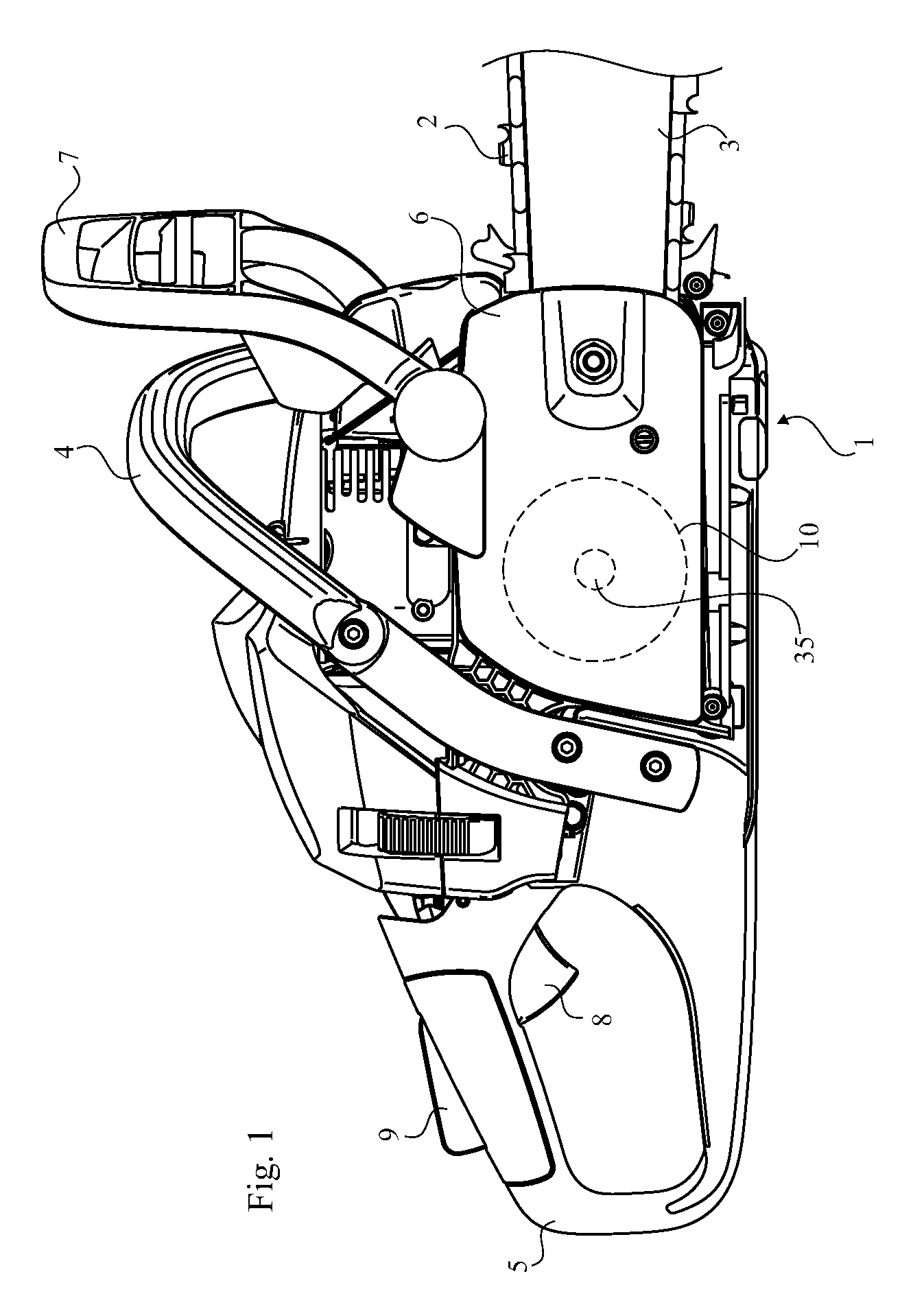
[0103]FIG. 1 is a side view of a chain saw, driven by a two-stroke engine, not shown. The chain saw has an engine housing 1, a saw chain 2, a saw chain guide bar 3, a front handle 4 for carrying the saw, a rear handle 5 for operating the saw, a detachable clutch cover 6 of the engine housing 1, and a hand guard 7 connected to a brake arrangement located inside of the clutch cover for rapidly stopping the rotation of the saw chain in case of a kickback of the saw. Thus the hand guard 7 acts as a kickback actuator for engaging the kickback brake.

[0104]A saw operating mechanism requiring a grip of at least one hand of an operator is provided in the rear han...


PUM

PropertyMeasurementUnit
speedaaaaaaaaaa
forceaaaaaaaaaa
force transmittingaaaaaaaaaa

Abstract

A chainsaw having a brake arrangement comprising: a kickback brake drum (10) arranged to rotate together with a drive sprocket driving a saw chain of a chainsaw, a kickback brake for quickly stopping the saw chain if at least one kickback actuator (7) is actuated, the kick back brake including a kickback brake band (11) extending around the kickback brake drum (10) and means for tightening the kickback brake band (17-19, 22) around the kickback brake drum (10), and; a coasting brake weaker than the kickback brake being arranged to brake the saw chain (2) unless a coasting actuator of the chainsaw is actuated, the coasting brake includes a coasting brake band extending around a coasting brake drum (10) arranged to rotate together with the drive sprocket (37), and means for tightening the coasting brake band (20, 22, 23) around the coasting brake drum, wherein the coasting brake band is either at least one longitudinally slit portion (11b) of the kickback brake band or a separate brake band.

Description

TECHNICAL FIELD[0001]A coasting brake arrangement for a power tool such as a chain saw, brush cutter or power cutter having a work tool such as a saw chain or saw blade, which coasting brake arrangement includes a speed controlling throttle trigger member and a force transmitting member having one end operatively connected to the throttle trigger member and another end operatively connected to a first brake member, which is biased towards a cooperating rotary second brake member that rotates when the work tool is running, so that the work tool is free to run when the throttle trigger member is pushed in but braked when the throttle trigger member is released to make the first brake member press against the second brake member in order to prevent the work tool from running.[0002]The present invention further relates to a chainsaw having a brake arrangement comprising:[0003]a saw chain wound around a guide bar, where said guide bar is an extension from a housing;[0004]a drive means fo...

Claims


Application Information

Patent Timeline
Patent Type & Authority Applications(United States)
IPC IPC(8): B27B17/02F16D49/10F16D65/16F16C1/12F16D55/22F16D51/12
CPCB27B17/083
Inventor MARTINSSON, PARANDERSSON, LARSENGMAN, THOMASROSBERG, BJORN
Owner HUSQVARNA AB
Why Eureka
Try Eureka