
Vehicle lamp module

a vehicle lamp module and lamp module technology, applied in fixed installation, transportation and packaging, light and heating equipment, etc., can solve the problems of increasing the cost of the continuous light-emitting diode package, the inability to meet relevant light sources, and the inability to use single light-emitting modules. to achieve the effect of reducing the cost of manufacturing

Active Publication Date: 2015-10-22
WANG CHENG
View PDF2 Cites 6 Cited by
  • Summary
  • Abstract
  • Description
  • Claims
  • Application Information

AI Technical Summary

Benefits of technology

The present disclosure provides a vehicle lamp module with multiple light-focal curved surfaces that can be made using a common process for light-emitting diodes. This design helps to avoid problems in the prior art and reduces manufacturing costs. The module meets relevant regulations and is especially suitable for a high-beam lamp structure. The technical effect is to provide a cost-effective and efficient solution for vehicle lamps that meets industry-specific standards.

Problems solved by technology

However, because a single elliptical lamp cup only has a single focal point, only a single light-emitting module can be used.
However, with the same brightness, the cost of the continuous light-emitting diode package is at least 10 times more than a common light-emitting diode manufactured through a common process.
Meanwhile, when the common light-emitting diode manufactured through the common process is mounted in a conventional vehicle lamp module, due to the design of the lamp cup of the conventional vehicle lamp module, a light source emitted by the conventional vehicle lamp module cannot meet relevant regulations such as ECE R112 in the Regulations of United Nations Economic Commission for Europe (ECE regulations for short) and the SAE J1383 regulation for the vehicle lamp standard of the Society of Automotive Engineering.
Therefore, if common illumination light-emitting diodes each having a size of 1 mm×1 mm are discretely arranged and the distance between adjacent ones in the light-emitting diodes is 0.5 mm, multiple light sources are thus formed, thus failing to meet the regulatory requirements.

Method used


Image

  • Vehicle lamp module
  • Vehicle lamp module
  • Vehicle lamp module

Examples


first embodiment

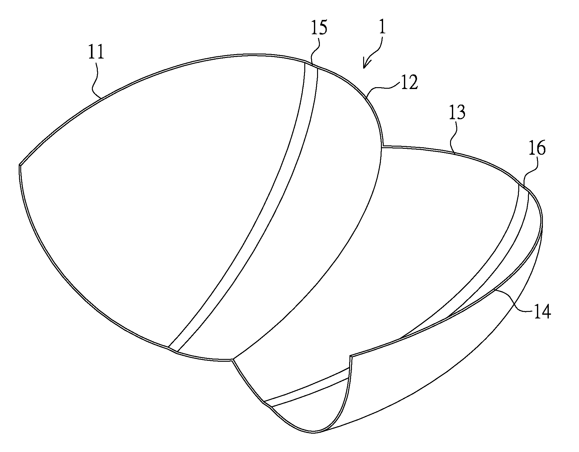
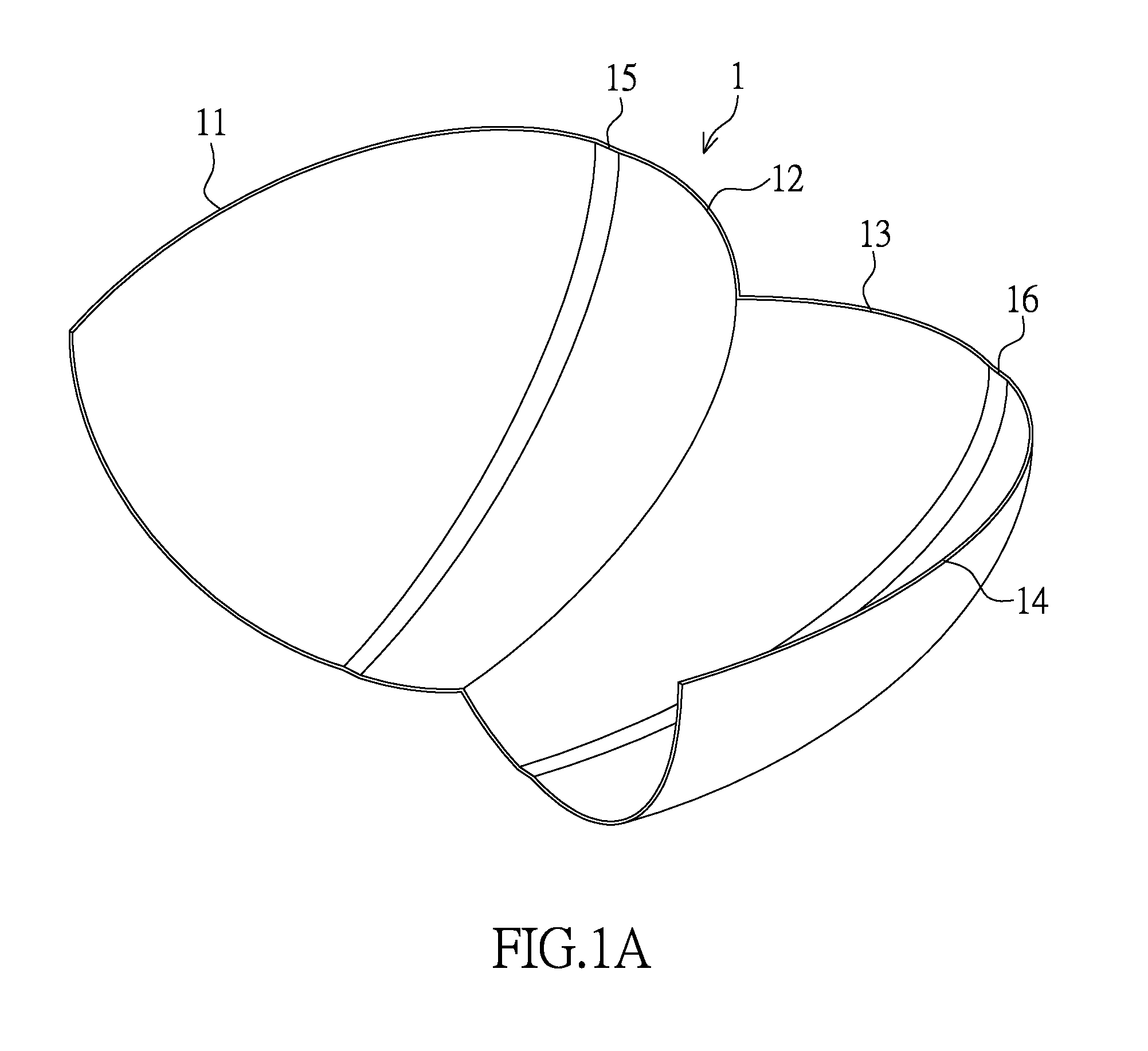
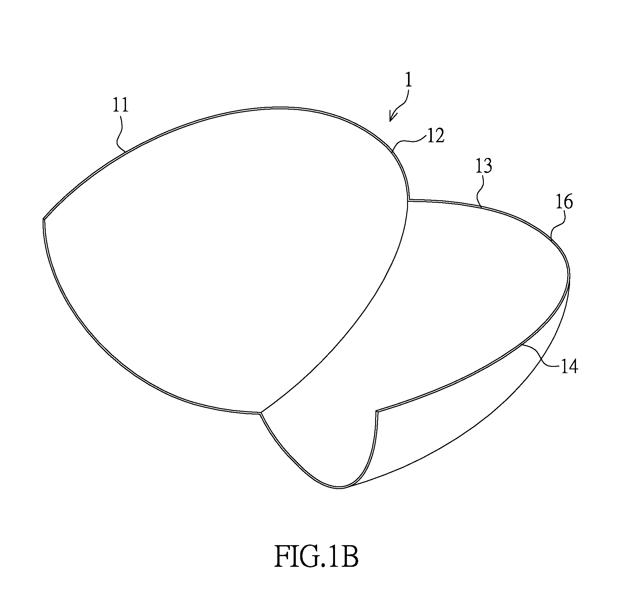
[0028]Firstly, referring to FIG. 1A to FIG. 1E, a first embodiment of the present disclosure provides a vehicle lamp module C, including a lamp cup structure (or lamp reflector structure) 1, a light-emitting structure 2, and a lens structure 3. As shown in FIG. 1A, the lamp cup structure 1 may consist of multiple curved surfaces with different curvatures. For example, the lamp cup structure may be formed of ellipse-based curved surfaces with different curvatures. In the first embodiment of the present disclosure, the lamp cup structure 1 has a first light-focusing curved surface 11, a second light-focusing curved surface 12, a third light-focusing curved surface 13, and a fourth light-focusing curved surface 14, where the lamp cup structure 1 may further have a first light-diffusing curved surface 15 disposed or connected between the first light-focusing curved surface 11 and the second light-focusing curved surface 12 and a second light-diffusing curved surface 16 disposed or conne...

second embodiment

[0037]Firstly, referring to FIG. 2A to FIG. 2C, a second embodiment of the present disclosure provides a vehicle lamp module C, including a lamp cup structure 1, a light-emitting structure 2, and a lens structure 3. As shown in FIG. 2A, the lamp cup structure 1 may consist of multiple curved surfaces with different curvatures. For example, the lamp cup structure 1 may be formed of ellipse-based curved surfaces with different curvatures. It can be understood by comparing FIG. 2A and FIG. 2B with FIG. 1B and FIG. 1C that, the greatest difference between the second embodiment and the first embodiment is that light-focusing curved surfaces are designed differently, and the curvatures of the light-focusing curved surfaces are changed such that axes along which light sources are projected through the light-focusing curved surfaces onto a reference line H of the lens structure 3 are changed.

[0038]As shown in FIG. 2A, in the second embodiment of the present disclosure, the lamp cup structur...

third embodiment

[0043]Referring to FIG. 2D, a schematic top view of a third embodiment of the present disclosure is shown. It can be understood by comparing FIG. 2C and FIG. 2D that, the greatest difference between the third embodiment and the second embodiment of the present disclosure lies in the design of light-focusing curved surfaces and configuration relationships among light-focusing curved surfaces and light-emitting elements. In the third embodiment, the curvatures of the second light-focusing curved surface 12 and the third light-focusing curved surface 13 originally in the second embodiment may be changed, so that the second light-focusing curved surface 12 and the third light-focusing curved surface 13 have the same curvature and thus the same focal point.

[0044]As shown FIG. 2D, the third embodiment of the present disclosure provides a vehicle lamp module C, including a lamp cup structure 1, a light-emitting structure 2, and a lens structure 3. The lamp cup structure 1 has a first light...


PUM


Abstract

Disclosed is a vehicle lamp module, including a lamp cup structure, a light-emitting structure, and a lens structure. The lamp cup structure has multiple light-focusing curved surfaces, where each of the light-focusing curved surfaces has a first focal point and a second focal point, and the first focal point and the second focal point of each light-focusing curved surface are located on an axis of the light-focusing curved surface. The light-emitting structure includes multiple light-emitting elements, where each of the light-emitting elements is disposed corresponding to the first focal point of a corresponding one of the light-focusing curved surfaces. The lens structure has a lens focal point, a primary optical axis, and a reference line, where the lens focal point is located at an intersection point of the primary optical axis and the reference line and the reference line is parallel to the lens structure.

Description

TECHNICAL FIELD[0001]The present disclosure relates to a vehicle lamp module, and in particular, to a vehicle lamp module with multiple light-focusing curved surfaces.BACKGROUND ART[0002]Light-emitting modules of conventional vehicle headlamps may be classified into tungsten halogen lamps and High Intensity Discharge (HID) lamps, where the tungsten halogen lamp has an arc length of 5.6 mm and the HID lamp has an arc length of 4.3 mm. In order to match with traditional illumination lamp sources, a Projector Ellipsoid System (PES) is most often used as a light-focusing system, where a lamp cup has the characteristic of a single optical axis and a single light-emitting module. At present, in order to match the arc lengths and sizes of a tungsten halogen lamp and an HID lamp, a light-emitting diode module disposed in the vehicle headlamp adopts a continuous light-emitting diode packaging process. However, because a single elliptical lamp cup only has a single focal point, only a single ...

Claims


Application Information

Patent Timeline
Patent Type & Authority Applications(United States)
IPC IPC(8): F21S8/10
CPCF21S48/1388F21S48/125F21S41/143F21S41/147F21S41/255F21S41/321F21S41/336F21S41/43F21S41/365F21S41/151
Inventor WANG, CHENG
Owner WANG CHENG
Learn More