Heating and cooling system for vehicle seat

a technology for heating and cooling systems and vehicle seats, which is applied in ventilation systems, heating types, lighting and heating apparatus, etc. it can solve the problems of heat rashes, occupants may feel chilly or cold in the buttocks or back, and the air conditioning system does not have a function of controlling the temperature of the vehicle seat, so as to improve the heating efficiency and improve the heating performance. , the effect of excellent heating performan

Inactive Publication Date: 2011-03-17
HYUNDAI MOTOR CO LTD +1
View PDF10 Cites 15 Cited by
  • Summary
  • Abstract
  • Description
  • Claims
  • Application Information

AI Technical Summary

Benefits of technology

[0027]First, since the seat is heated using the PTC element having excellent heating performance, the efficiency of the heater can be raised when compared to the conventional heating using the Peltier element. Accordingly, the heating of the vehicle seat and the power efficiency can be improved.
[0028]Second, since the heating is performed using the PTC element, it is not necessary to convert the direction of a current supplied to the Peltier element unlike the related art. As a result, the circuit configuration is simplified.

Problems solved by technology

However, the air-conditioning system does not have a function of controlling the temperature of a vehicle seat.
Then, the occupant may sweat at the buttocks and the back, which would otherwise develop into heat rashes.
In the winter, even if the occupant sitting on the vehicle seat raises the temperature inside the vehicle by operating the heater, the occupant may feel chilly or cold at the buttocks or back since the seat has stayed cold for a long time before the heater is operated.
However, the problem of the thermoelectric element is that the efficiency of a heating part is about 50% of that of a cooling part under the same power supply conditions.
However, in the case of heating the seat, the low efficiency of the heating part of the thermoelectric element increases power consumption, thereby lowering the efficiency of the heating and cooling system.

Method used


Image

  • Heating and cooling system for vehicle seat
  • Heating and cooling system for vehicle seat
  • Heating and cooling system for vehicle seat

Examples


Embodiment Construction

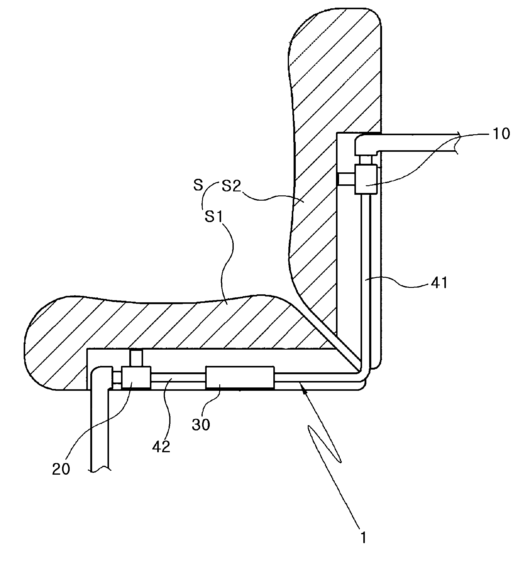
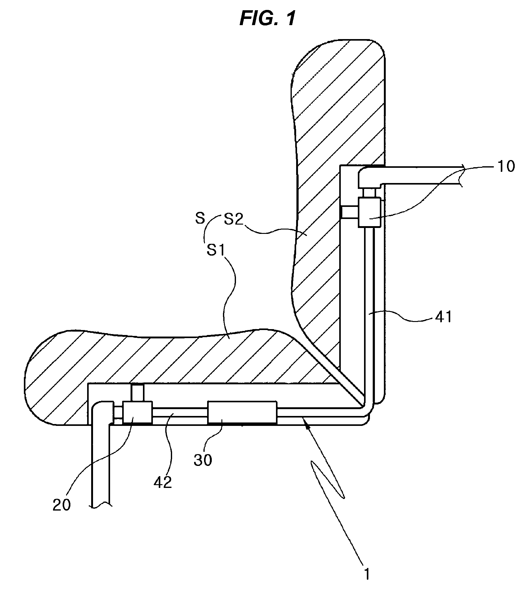
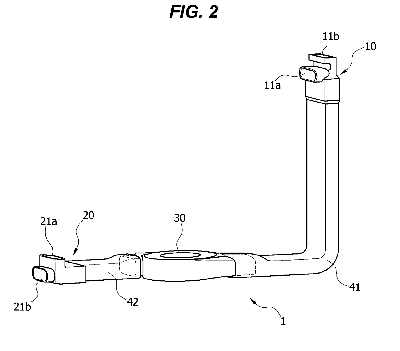
[0041]Reference will now be made in detail to various embodiments of the present invention(s), examples of which are illustrated in the accompanying drawings and described below. While the invention(s) will be described in conjunction with exemplary embodiments, it will be understood that present description is not intended to limit the invention(s) to those exemplary embodiments. On the contrary, the invention(s) is / are intended to cover not only the exemplary embodiments, but also various alternatives, modifications, equivalents and other embodiments, which may be included within the spirit and scope of the invention as defined by the appended claims. Above all, reference should be made to the drawings, in which the same reference numerals and signs are used throughout the different drawings to designate the same or similar components. In the following description of the present invention, a detailed description of known functions and components incorporated herein will be omitted...


PUM


Abstract

A heating and cooling system for a vehicle seat, may include a heat exchanger cooling or heating air before the air is introduced into the seat, and a blower blowing air toward the heat exchanger, wherein the heat exchanger includes a positive temperature coefficient element assembly provided inside a housing of the heat exchanger to heat the air supplied from the blower, and wherein the positive temperature coefficient element assembly operates in a case of heating the seat but does not operate in a case of cooling the seat.

Description

CROSS REFERENCE TO RELATED APPLICATION[0001]The present application claims priority to Korean Patent Applications Number 10-2009-0088222 filed on Sep. 17, 2009 and 10-2010-0050013 filed on May 28, 2010 the entire contents of which applications are incorporated herein for all purposes by this reference.BACKGROUND OF THE INVENTION[0002]1. Field of the Invention[0003]The present invention relates to a heating and cooling system for a vehicle seat, and more particularly, to one which can enhance power efficiency by efficiently cooling and heating the vehicle seat.[0004]2. Description of Related Art[0005]In general, a vehicle is equipped with an air-conditioning system including a cooler and a heater. The air-conditioning system serves to control the temperature inside the vehicle. However, the air-conditioning system does not have a function of controlling the temperature of a vehicle seat. In the summer, even if an occupant sitting on a vehicle seat lowers the temperature inside the ve...

Claims


Application Information

Patent Timeline
Patent Type & Authority Applications(United States)
IPC IPC(8): F25B21/04F24F7/007F28F7/00
CPCB60N2/5692B60N2/5657
Inventor JUN, DUCK CHAEJEONG, WOOKOH, MAN JUPARK, JANG SU
Owner HYUNDAI MOTOR CO LTD
Why Eureka
Try Eureka