Hand winch with brake and freewheel

a freewheel and hand winch technology, applied in the field of hand winches, can solve the problems of friction brake activation, slippage and relative rotation of the gear member and the shaft, etc., and achieve the effects of increasing the inertia of the shaft, increasing the friction resistance, and rapid activation of the friction brak

Active Publication Date: 2011-03-17
GUYARD FRANCOIS XAVIER
View PDF11 Cites 6 Cited by
  • Summary
  • Abstract
  • Description
  • Claims
  • Application Information

AI Technical Summary

Benefits of technology

[0024]In a further embodiment, a torque threshold maximally transferable from the gear member to the shaft and corresponding to the increased friction resistance, is less than 5 Nm, particularly less than 2 Nm, more particularly less than 1 Nm, more particularly less than 0.3 Nm, in particular less than 0.05 Nm, especially less than 0.01 Nm. The low threshold torque enables rapid activation of the friction brake as soon as a minor counter torque is applied to the shaft, for example by the user.
[0025]In a preferred embodiment of the invention, the friction resistance of the friction means is adjusted such that the inertia of the shaft can be entrained by the gear member via the friction means, but in the case of an increased inertia of the shaft caused by adding an additional inertia mass, in particular the crank handle, the entraining torque of the gear member cannot be transferred to the shaft by way of the friction means. Even if the torque between the gear member and the shaft results from merely pulling the elongated member without load, the torque cannot be transferred into the shaft when the additional inertia mass is mounted, since the frictional resistance of the friction means is not sufficiently high. Only by unmounting the additional inertia mass the shaft is entrained and the friction brake is deactivated. Thus, the friction brake cannot be deactivated when the crank handle is mounted on the shaft. Furthermore the hand winch of the device herein assures that a mounted crank handle cannot be driven in rotation by the gear member, and thus, the risk of injury for an operator is essen

Problems solved by technology

In the case that the driving force between the shaft and the gear member overcomes the increased frictional resistance, slippage and relative rotation may occur between the gear member and the shaft.
Only if an external resistance applied to the shaft beco

Method used


Image

  • Hand winch with brake and freewheel
  • Hand winch with brake and freewheel
  • Hand winch with brake and freewheel

Examples


Embodiment Construction

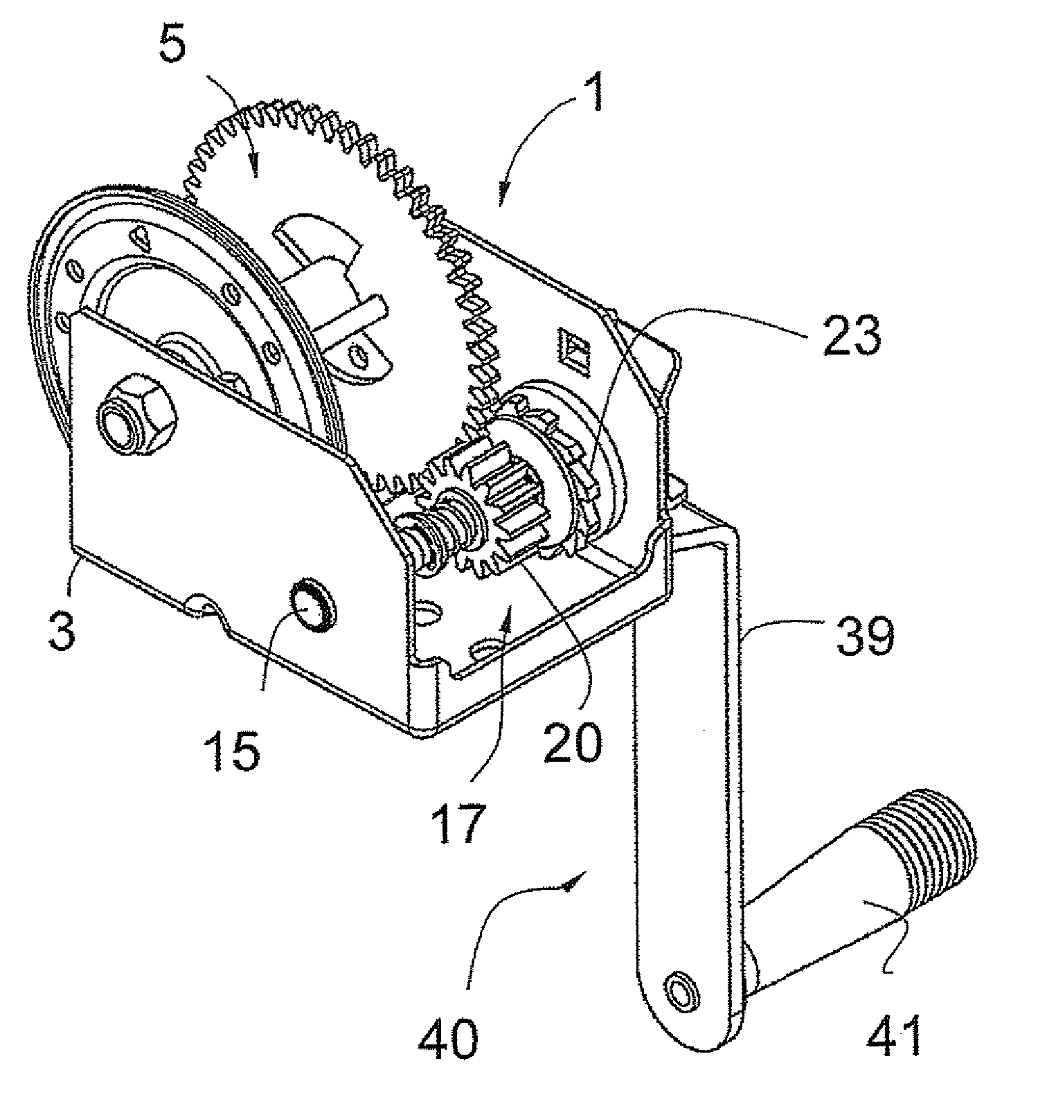
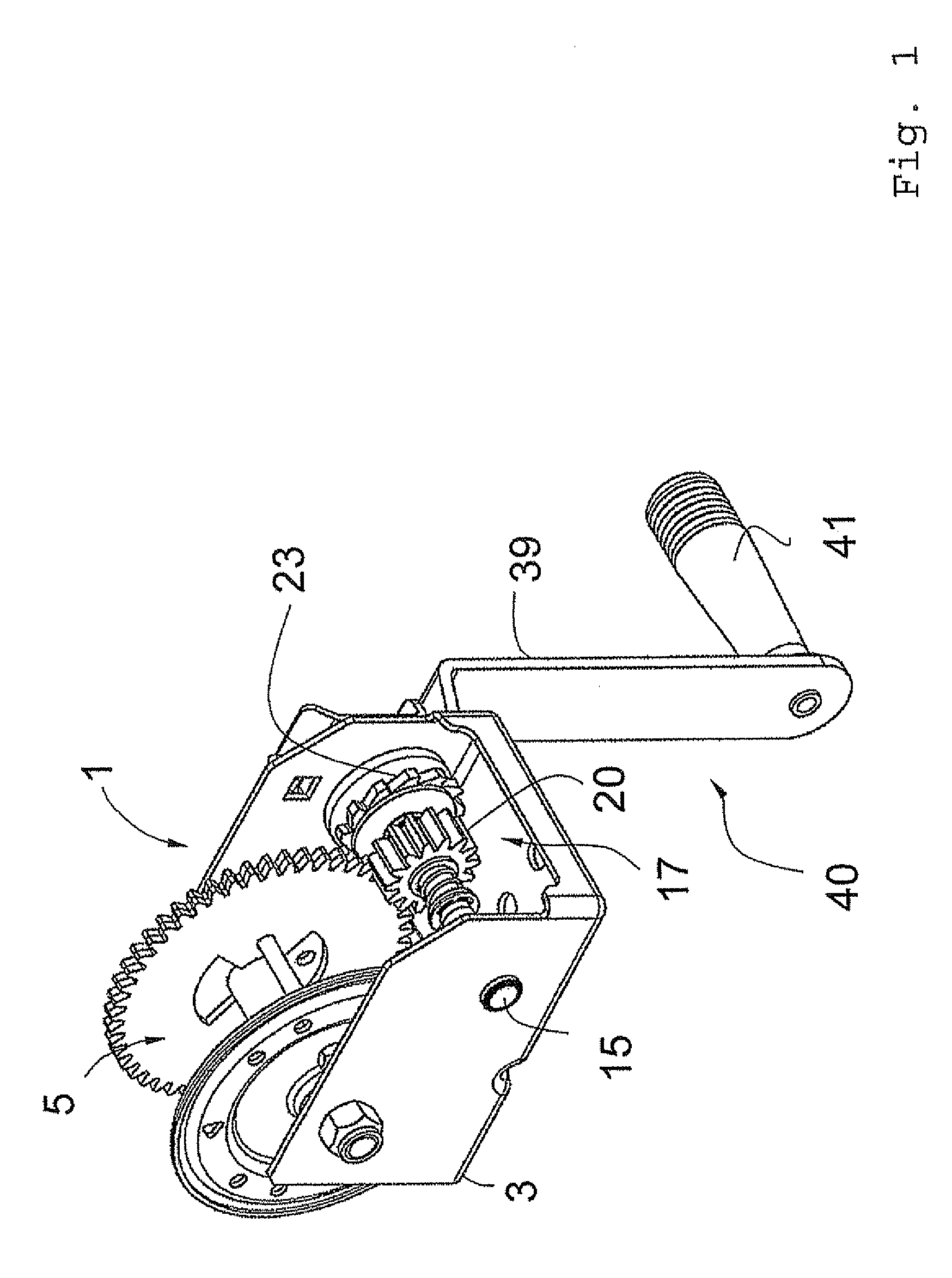
[0070]In FIGS. 1 to 3, the hand winch according to a preferred embodiment of the invention is generally denoted with the reference numeral 1. While FIGS. 1 and 2 show the hand winch in the release position, FIG. 3 shows the hand winch in a brake position. In the description to follow, the main elements of the hand winch according to the preferred embodiment of the invention are introduced.

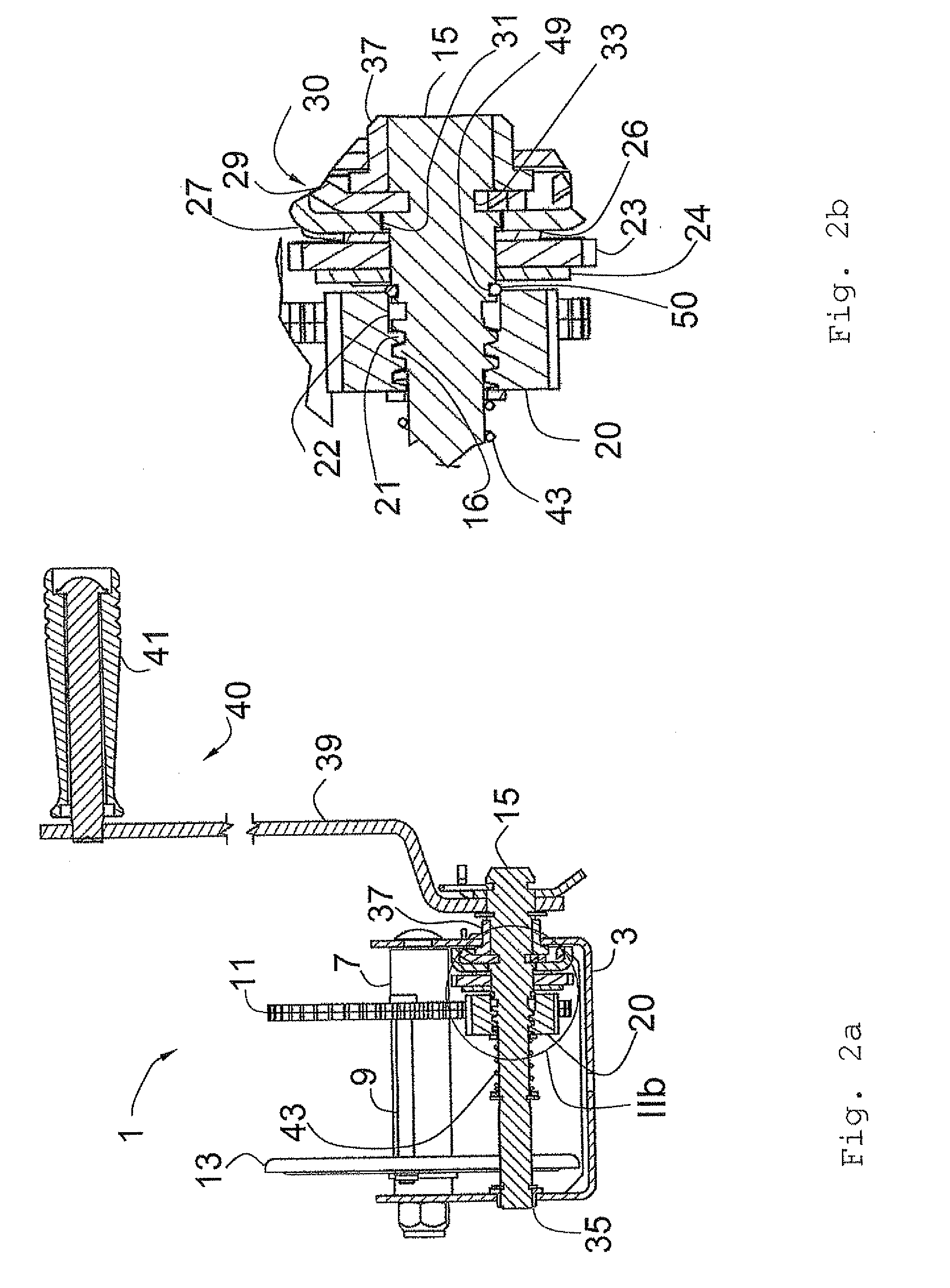
[0071]The hand winch 1 comprises a housing 3 which has a U-shaped cross section. Between two side walls of the housing 3 representing the legs of the U primary axis 7 of winding roll 5 is mounted. The winding roll 5 further comprises a securing bar 9 for securing a flexible elongated member on the primary axis. In this embodiment, the flexible elongated member is a belt for winding up a boat (not shown). The winding roll 5 further comprises a gear wheel 11 and a side plate 13 for giving lateral support to the belt as it is wound up.

[0072]Furthermore, a shaft 15 is mounted at the housing 3, passing ...


PUM


Abstract

A hand winch including a winding roll, a flexible elongated member, a shaft connected to the winding roll, a friction brake including a brake disk and a gear element engaging the winding roll and mounted on the shaft. The gear element has a release position and a brake position in which the gear element enters into frictional contact with the brake disk, generating a braking torque resisting winding off the flexible elongated member. Friction means is provided between the shaft and the gear element for generating a frictional resistance therebetween such that, if a driving force acting on the gear element does not overcome the frictional resistance established by the friction means, the gear element drives the shaft through friction means. However, if the driving force between the shaft and the gear element overcomes the frictional resistance, relative movement between the gear element and the shaft occurs.

Description

CLAIM OF PRIORITY[0001]Applicant claims foreign priority benefits under Title 35, United States Code, Section 119(a)-(d) or (f), or 365(b), of the foreign patent application identified following: Foreign Application No. EP 09 010 459.7, filed in the European Patent Office, having a Filing Date of Aug. 13, 2009.BACKGROUND OF THE INVENTION[0002]1. Field of the Invention[0003]The invention refers to a hand winch which comprises a rotating winding roll for winding up and winding off a flexible elongated member, such as a belt, a band, a cable or the like.[0004]2. Description of the Prior Art[0005]Typically, prior art hand winches included a rotatable rotation shaft engaged with a winding roll for transmitting manual operating forces via a crank handle connected to the shaft for rotating the winding roll. Further, specific hand winches have included an automatically activating friction brake such that the friction brake is activated automatically when a pulling load is applied to the elo...

Claims


Application Information

Patent Timeline
IPC IPC(8): B65H75/18B65H75/30
CPCB66D1/06B66D5/22B66D1/14
Inventor GUYARD, FRANCOIS-XAVIER
Owner GUYARD FRANCOIS XAVIER
Why Eureka
Try Eureka