Stereoscopic image display apparatus

a stereoscopic image and display apparatus technology, applied in the field of stereoscopic image display apparatus, can solve the problems of inability to adjust the image according to the actual level of fatigue, the viewer's asthenopia may be increased more than expected, and the generated stereoscopic image lacks stereoscopic effect and a sense of reality, etc., to achieve accurate measurement and achieve the effect of stereoscopic viewing quality

Inactive Publication Date: 2011-03-17
FUJIFILM CORP
View PDF10 Cites 52 Cited by
  • Summary
  • Abstract
  • Description
  • Claims
  • Application Information

AI Technical Summary

Benefits of technology

[0034]According to the presently disclosed subject matter, the fusion limit of each viewer is measured beforehand, and a stereoscopic image is outputted while the parallax of the stereoscopic image is controlled so as not to exceed the fusion limit of the viewer. Thereby, it is possible to provide a stereoscopic image which can be viewed by each viewer in the state where the stereoscopic effect and the sense of reality are maximized for the viewer. Further, the level of asthenopia of the viewer can be accurately measu...

Problems solved by technology

In particular, since the fusion limit is different for each viewer, there is a problem that when a stereoscopic image is generated according to the fusion limit of all viewers, the generated stereoscopic image lacks stereoscopic effect and a sense of reality.
However, the switching of the images is not performed according to an actual level of fatigue.
Thus, even when viewing a stereoscopic image causing less fatigue, the viewer cannot experience the stereoscopic effect for a long time, while when viewing a stereosc...

Method used


Image

  • Stereoscopic image display apparatus
  • Stereoscopic image display apparatus
  • Stereoscopic image display apparatus

Examples


first embodiment

[0070]Next, a first embodiment of a stereoscopic image display apparatus according to the presently disclosed subject matter will be described.

[0071]As shown in FIG. 6, when a stereoscopic image (for example, a slide show of 3D still images and a 3D moving image) is displayed by the stereoscopic image display apparatus, the information on the fusion limit of a viewer is first acquired (step S10).

[0072]The method for acquiring the information on the fusion limit of the viewer will be described with reference to FIG. 7.

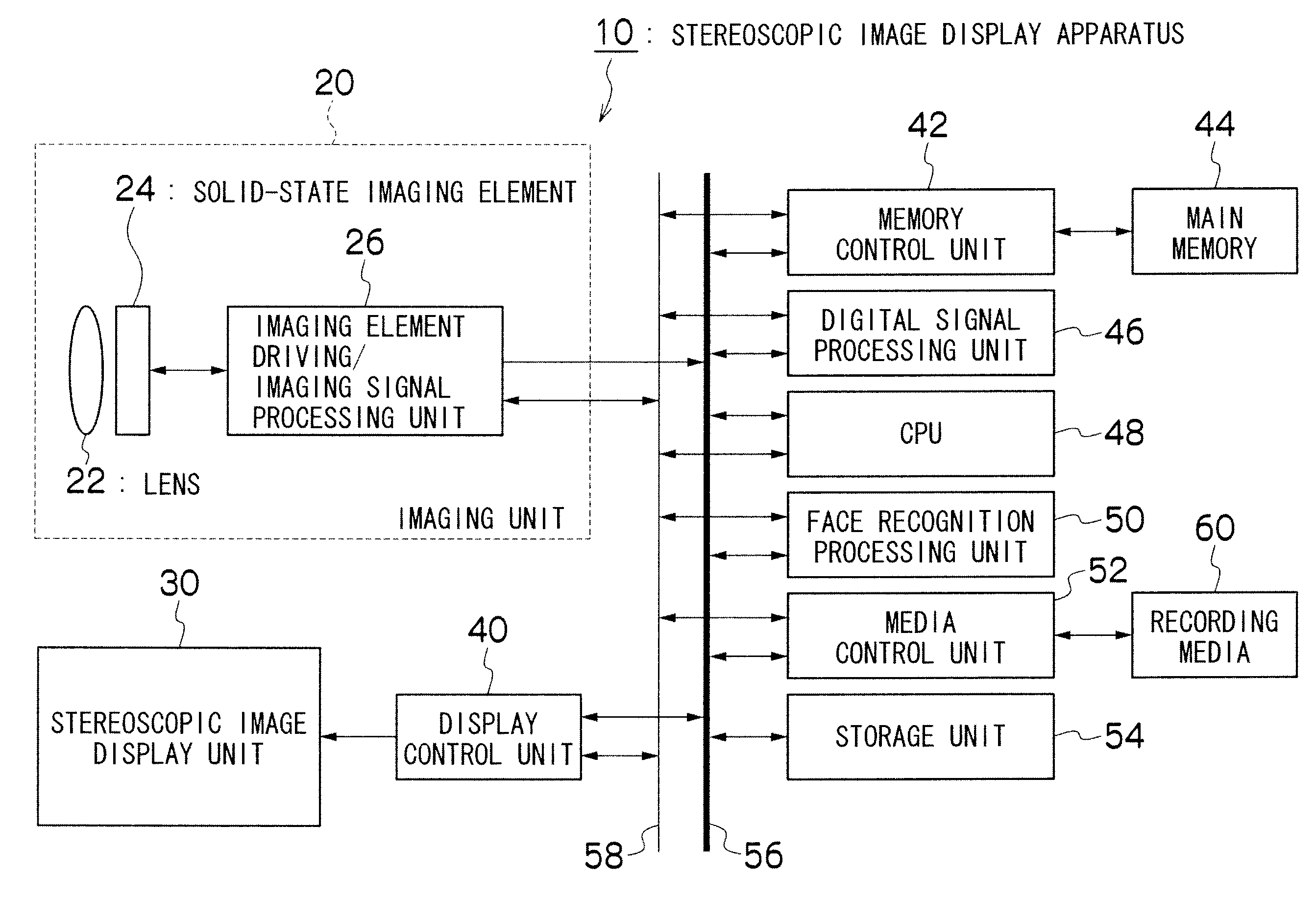
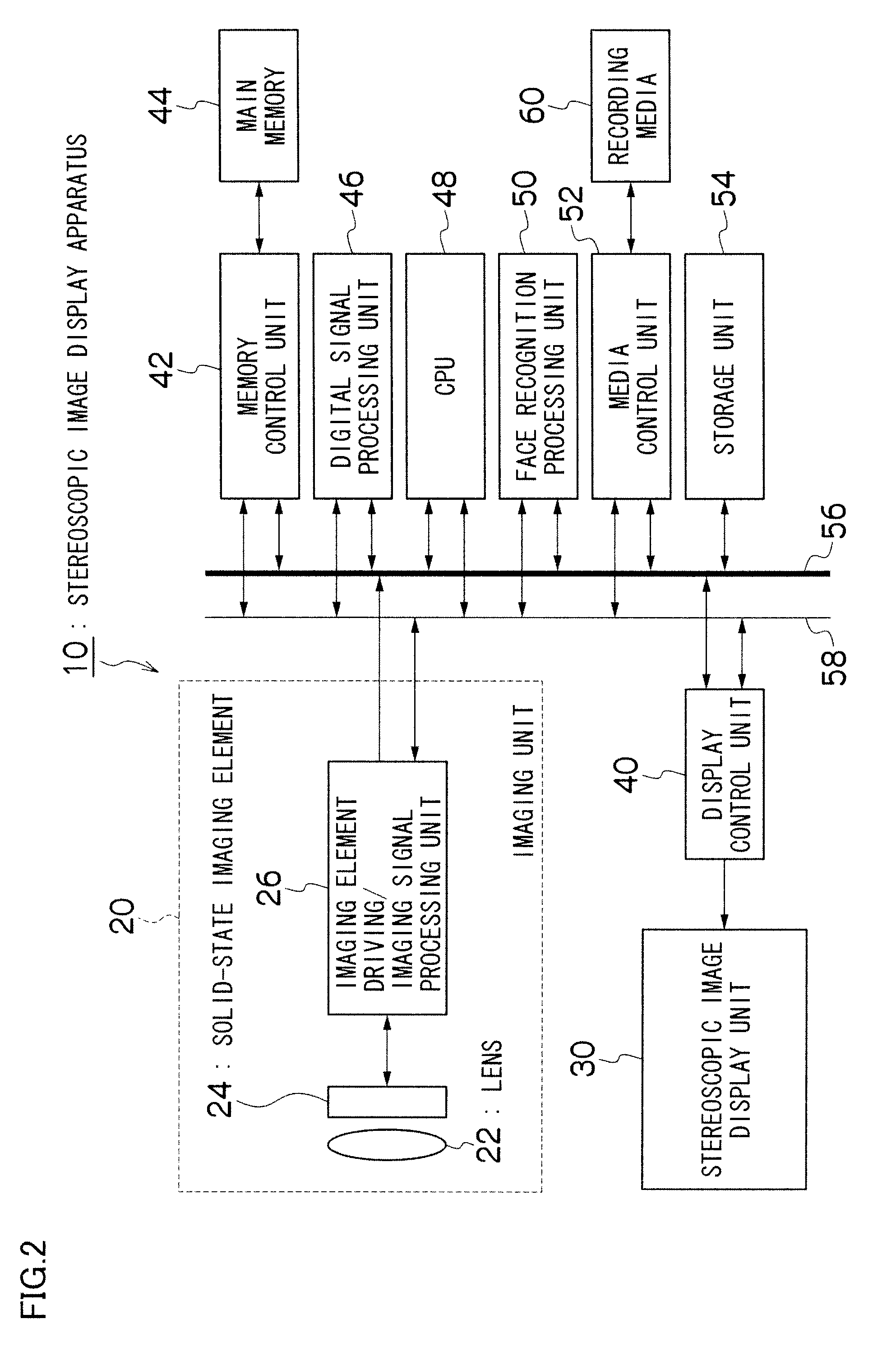
[0073]The CPU 48 turns on the power source of the camera (imaging unit 20) mounted on the stereoscopic image display apparatus 10 (step S20), and makes the camera photograph the viewer (including the face of the viewer) (step S22). The face recognition processing unit 50 detects a face image from the photographed image, and performs face recognition on the basis of the characteristic amounts of the detected face image (step S24).

[0074]When it is determined that the face...

second embodiment

[0084]Next, a second embodiment of a stereoscopic image display apparatus according to the presently disclosed subject matter will be described.

[0085]A stereoscopic image is photographed by a method shown in FIG. 10. Two cameras for respectively photographing L and R images are arranged in a state where the optical axes of the two cameras are arranged in parallel with each other or arranged to form a slight (convergence) angle, and a subject is simultaneously photographed by the two cameras to obtain a stereoscopic image.

[0086]The parallax of the obtained stereoscopic image is changed according to the conditions such as an interval between the two cameras (base line length), the angle (convergence angle) formed by the optical axes, and the distance to the subject. For example, when the photographing distance is different (distances a, b and c) in the camera arrangement shown in FIG. 10, the images shown in FIG. 11A to FIG. 11C are obtained by photographing the subject at the respect...

third embodiment

Modification of Third Embodiment

[0121]Next, a modification of the third embodiment of the stereoscopic image display apparatus according to the presently disclosed subject matter will be described.

[0122]FIG. 17 is a block diagram showing an internal configuration of a stereoscopic image display apparatus according to the modification of the third embodiment. Note that the same portions as those of the block diagram shown in FIG. 14 are designated by the same reference numerals and characters, and the detailed explanation thereof is omitted.

[0123]As shown in FIG. 17, this stereoscopic image display apparatus 10″ is different mainly in the stereoscopic image display system from the stereoscopic image display apparatus 10′ shown in FIG. 14. The stereoscopic image display apparatus 10″ includes, in place of the left-and-right image addition processing unit 70, a plane sequential converting unit 80 of left and right images, a left-and-right switching control unit 82, and liquid crystal s...


PUM


Abstract

To make it possible to stably provide a stereoscopic image which can be viewed by each viewer in the state where the stereoscopic effect and the sense of reality are maximized. Left eye and right eye images (images for measurement), the parallax between which is continuously or stepwise changed, are outputted beforehand to a stereoscopic image display device, and the face of the viewer viewing the images for measurement is photographed. The pupil width of the photographed viewer is measured, and based on the state of the change in the pupil width, the fusion limit of the viewer is measured and registered. In the case where a stereoscopic image for appreciation is displayed, the stereoscopic image is outputted by controlling the parallax of the stereoscopic image so as to prevent the parallax from exceeding the fusion limit of the viewer, which is measured beforehand.

Description

BACKGROUND OF THE INVENTION[0001]1. Field of the Invention[0002]The presently disclosed subject matter relates to a stereoscopic image display apparatus, and more particularly to a stereoscopic image display apparatus by which a stereoscopic image formed of left eye and right eye images having parallax therebetween is displayed so as to be able to be viewed stereoscopically.[0003]2. Description of the Related Art[0004]In a stereoscopic image display apparatus of this type, parallax between left eye and right eye images needs to be increased in order to enhance the stereoscopic effect and the sense of reality. However, the stereoscopic image display apparatus has a problem that when the binocular parallax exceeds the fusion limit of the viewer, the images cannot be stereoscopically viewed.[0005]Here, the left and right eye images having parallax therebetween respectively enter the left and right eyes of the viewer, and the parallax images are fused in the brain, so that the viewer ca...

Claims


Application Information

Patent Timeline
IPC IPC(8): H04N13/04H04N15/00H04N13/02
CPCH04N13/0003H04N13/0022H04N13/0033H04N13/007H04N13/0239H04N13/0257H04N2213/008H04N13/0425H04N13/0438H04N13/0484H04N13/0497H04N2213/002H04N13/0404H04N13/341H04N13/305H04N13/183H04N13/257H04N13/144H04N13/10H04N13/239H04N13/128H04N13/327H04N13/383H04N13/398
Inventor KUBOTA, MASAKATSU
Owner FUJIFILM CORP
Why Eureka
Try Eureka