Contact pin socket

a contact pin and socket technology, applied in the direction of coupling contact members, coupling device connections, two-part coupling devices, etc., can solve the problems of short circuit or poor electrical contact, and achieve the effect of reducing metal fatigue, increasing elastic softness, and reducing metal fatigu

Inactive Publication Date: 2011-03-17
CHENG SHENG HSIUNG
View PDF0 Cites 5 Cited by
  • Summary
  • Abstract
  • Description
  • Claims
  • Application Information

AI Technical Summary

Benefits of technology

[0006]In light of the shortcomings of the aforementioned prior art structure, the inventor of the present invention, having accumulated years of experience in related arts, has meticulously carried out extensive study and exploration to ultimately design a new improved contact pin socket. And a primary objective of the present invention is to provide a contact pin socket which is able to reduce metal fatigue and increase elastic softness.
[0007]In order to achieve the aforementioned objective, two sides of a bottom portion of the contact pin socket of the present invention are respectively formed with first folded plates and second folded plates, and first bent portions are respectively formed between the first folded plates and the second folded plates. Accordingly, the first folded plates and the second folded plates respectively formed on the two sides of the contact pin socket are able to disperse the applied force produced when a contact pin is inserted into the contact pin socket and firmly grip the contact pin, as well as reducing metal fatigue and prolonging operational life of the contact pin socket.

Problems solved by technology

Accordingly, electrical contact is degraded, resulting in a short circuit or poor electrical contact, and hence there is a need for improvement.

Method used


Image

  • Contact pin socket
  • Contact pin socket
  • Contact pin socket

Examples


Embodiment Construction

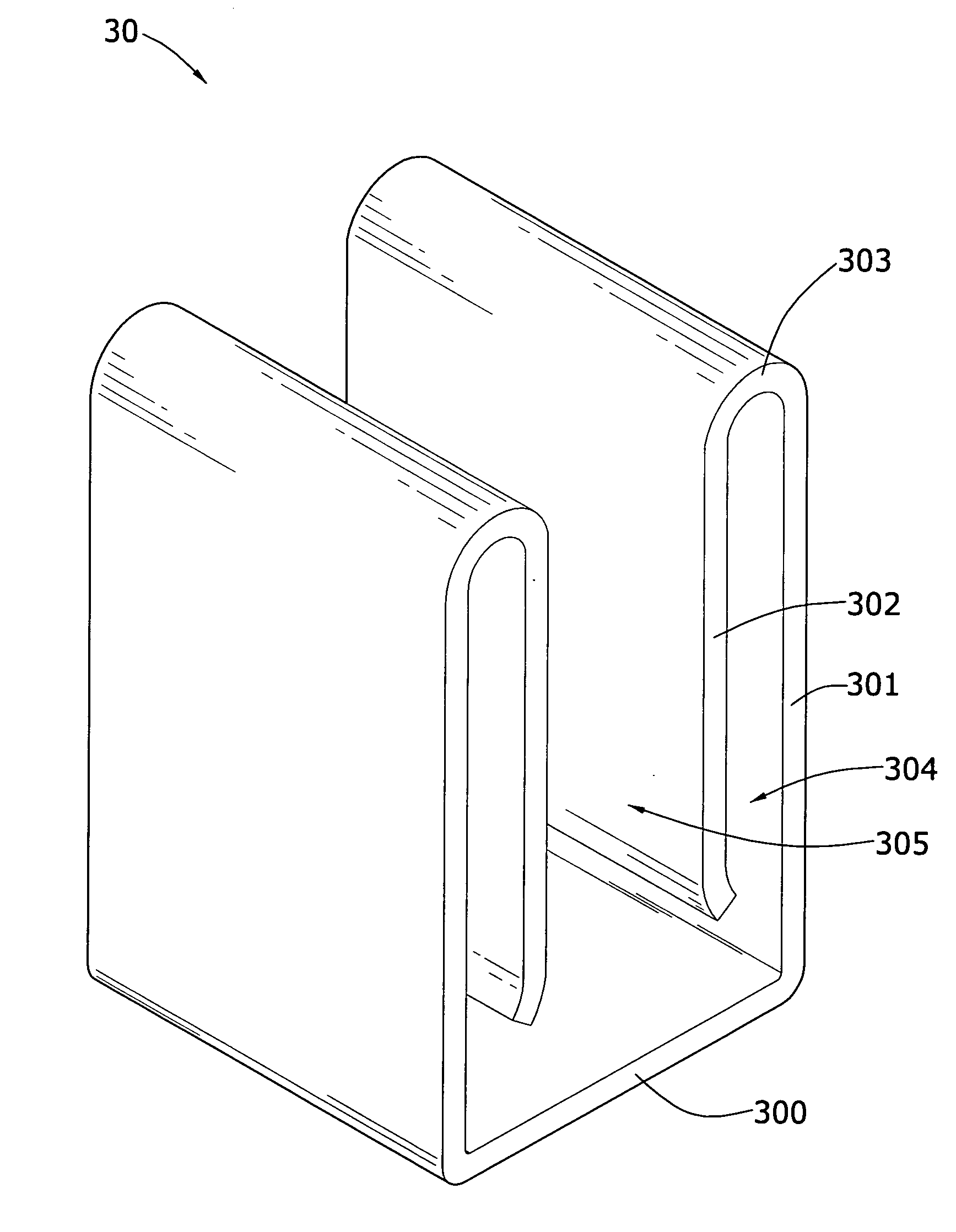
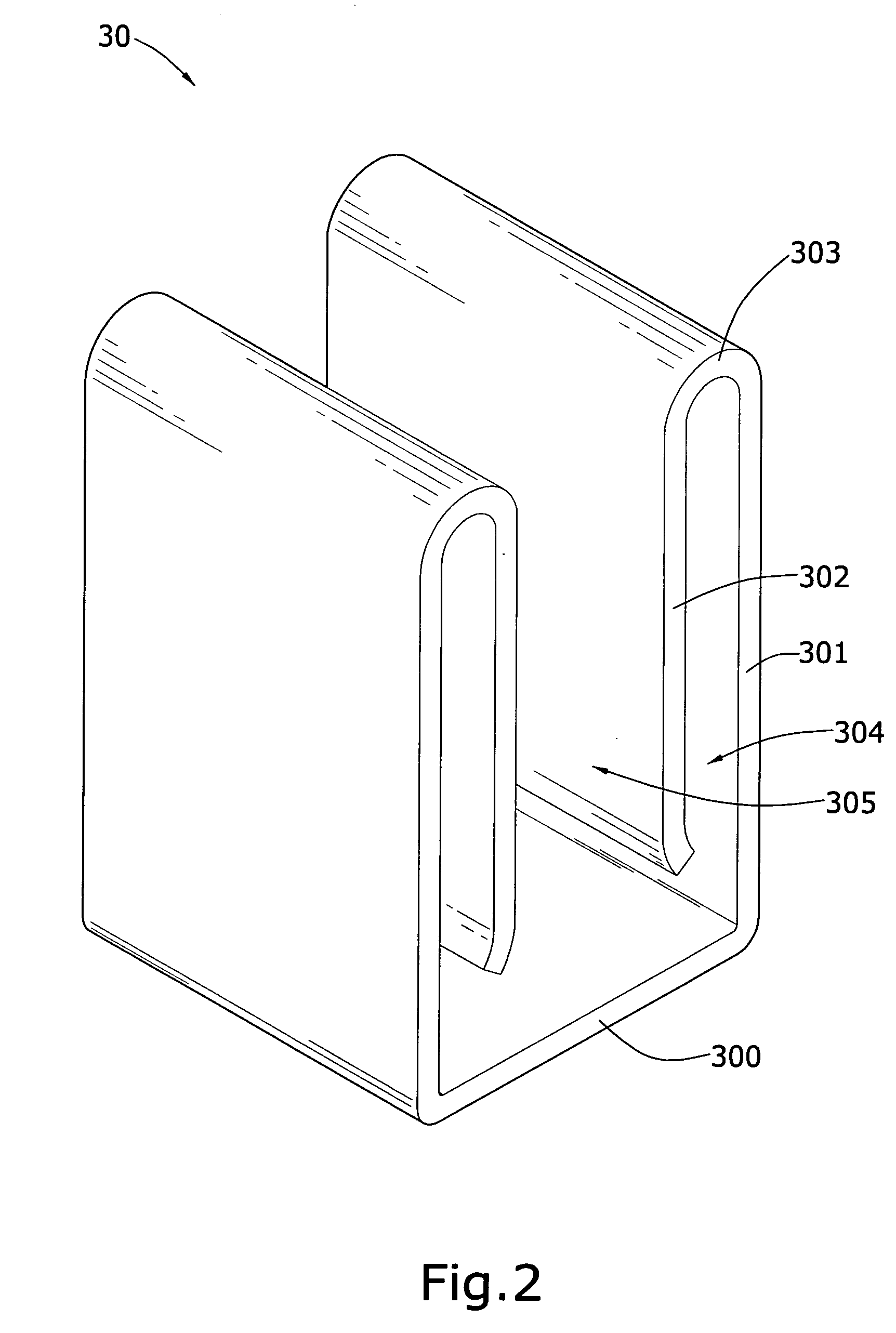
[0017]Referring to FIG. 2, which shows a structural schematic view of a preferred embodiment according to the present invention, wherein a contact pin socket 30 is a metallic bent member, which primarily comprises a bottom plate 300, two sides of which are respectively upwardly bent to form first folded plates 301, and ends of the first folded plates 301 respectively form bent portions 303 which are respectively inwardly bent towards the inner sides of the first folded plates 301 to form second folded plates 302. The first folded plates 301 and the second folded plates 302 are approximately parallel, and gaps 304 are respectively formed between the first folded plates 301 and the second folded plates 302; moreover, a slot 305 is formed between the two second folded plates 302.

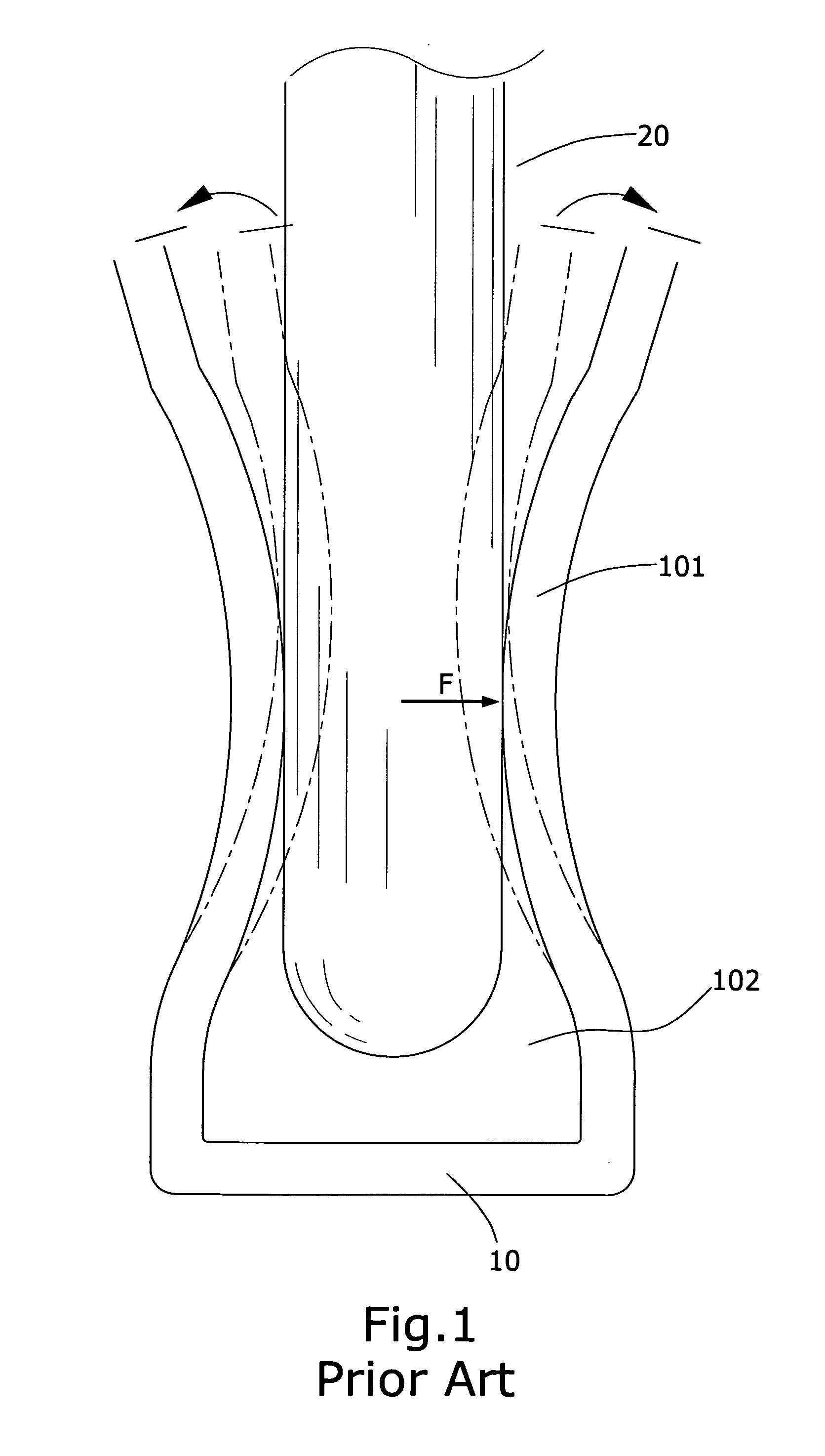
[0018]Referring to FIG. 3 and FIG. 4, which show cutaway views (1), (2) respectively depicting implementations according the preferred embodiment, and as depicted in FIG. 3, when a contact pin 20 is inserted in...


PUM


Abstract

A contact pin socket that is installed within a plug socket, and which is able to form an electrical connection with a contact pin set of a plug, wherein two sides of a bottom portion respectively form upwardly extending first folded plates, and top ends of the two sides are respectively inwardly bent and extend towards the inner sides of the first folded plates to form second folded plates. Accordingly, elasticity and deformation amount of the first folded plates and the second folded plates are used to disperse the applied force produced when contact pins are inserted, moreover, elastic softness of the contact pin socket is increased when subjected to an applied force, thereby effectively reducing elastic metal fatigue of the contact pin socket.

Description

BACKGROUND OF THE INVENTION[0001](a) Field of the Invention[0002]The present invention relates to a contact pin socket that is installed within a plug socket, and which is able to disperse the applied force produced when contact pins are inserted, thereby increasing elastic softness of the contact pin socket and reducing the possibility of permanent deformation of the contact pin socket.[0003](b) Description of the Prior Art[0004]Referring to FIG. 1, which shows a cutaway view of a contact pin socket of the prior art, which primarily comprises a contact pin socket 10 provided with a slightly U-shaped cross-sectional form, and a slot 102 is formed at the center of the contact pin socket 10. Inwardly protruding circular arc-shaped contact portions 101 are formed at centers of the two sides of the slot 102 of the contact pin socket 10, and the protruding contact portions 101 are provided with the effectiveness to grip a contact pin 20, thereby enabling a tighter electrical connection b...

Claims


Application Information

Patent Timeline
Patent Type & Authority Applications(United States)
IPC IPC(8): H01R13/11
CPCH01R13/115H01R2103/00H01R43/16H01R24/76
Inventor CHENG, SHENG-HSIUNG
Owner CHENG SHENG HSIUNG
Why Eureka
Try Eureka