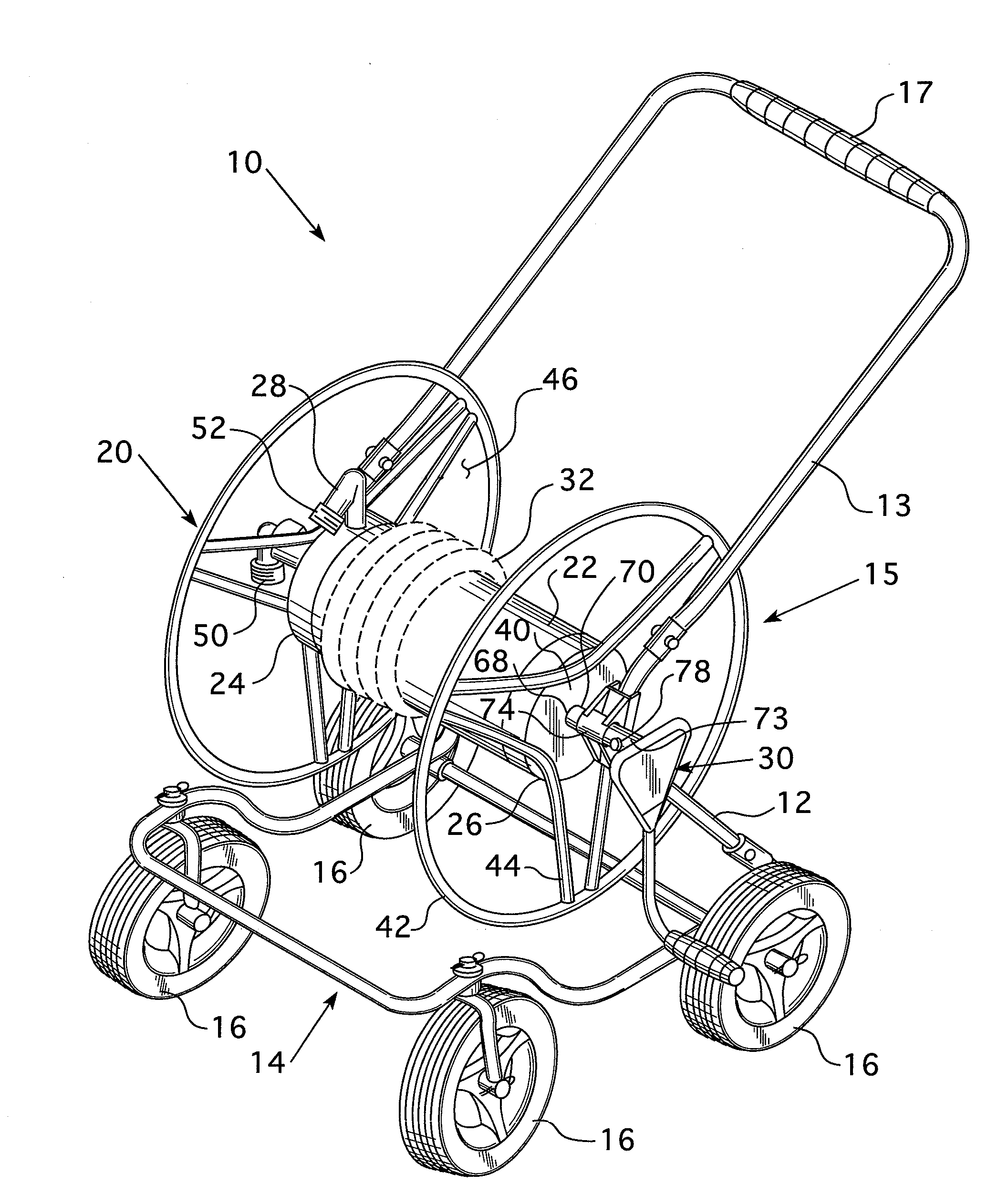
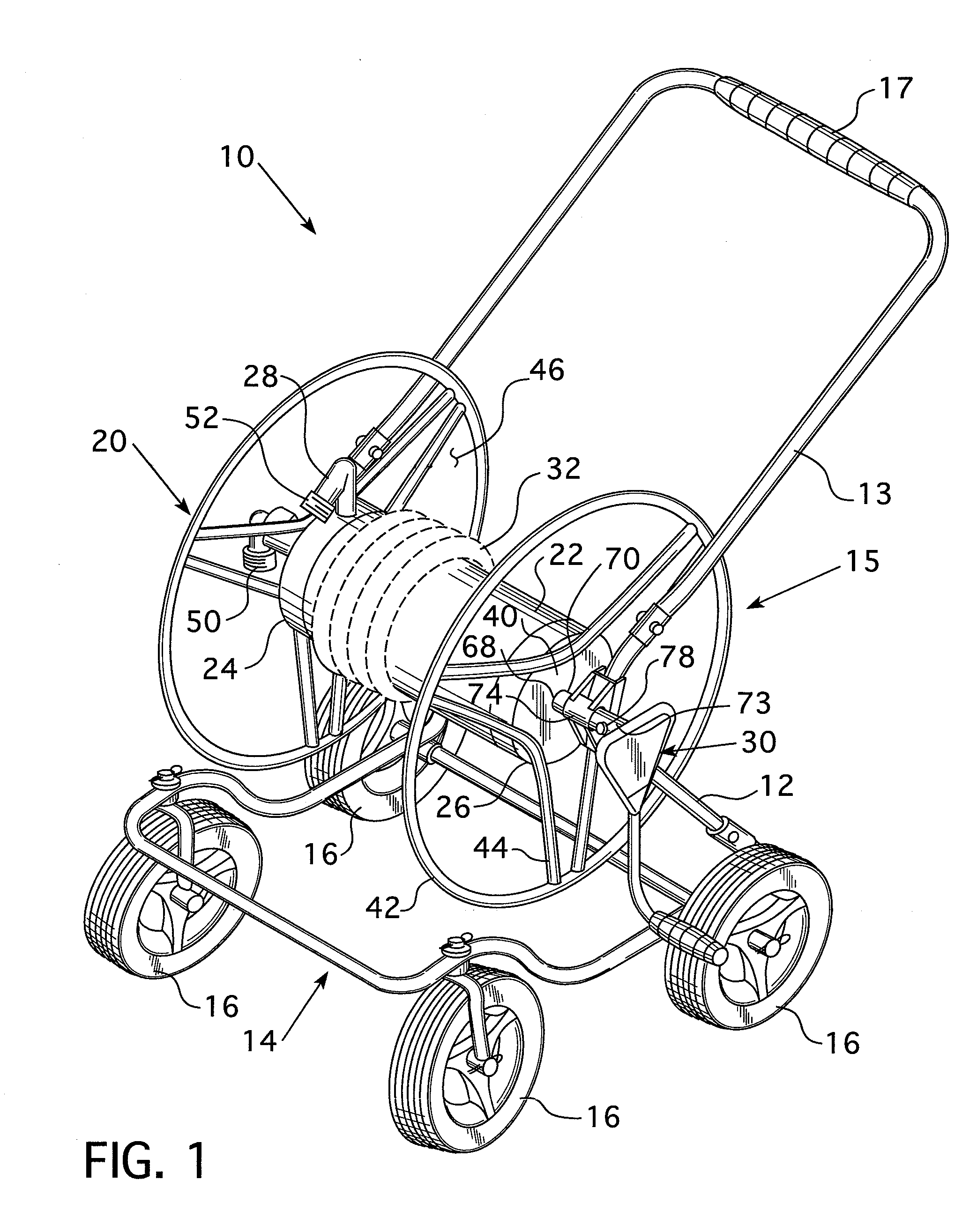
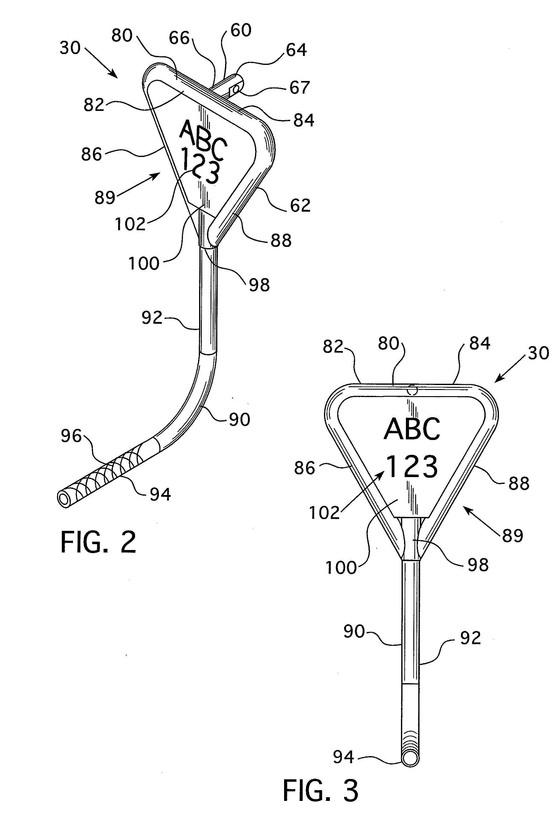
Triangular crank

a triangular crank and crank arm technology, applied in the direction of instruments, mechanical control devices, thin material processing, etc., to achieve the effect of increasing the length of the crank arm, reducing the effort required to bring in the hose, and prolonging the crank arm

Inactive Publication Date: 2011-03-17
IAMS
View PDF7 Cites 0 Cited by
  • Summary
  • Abstract
  • Description
  • Claims
  • Application Information

AI Technical Summary

Benefits of technology

[0006]The disclosed and claimed concept relates to a crank assembly for a hose reel and, more specifically, to a triangular crank assembly for a hose reel. It is noted that one method of reducing the effort required to bring in a hose would be to simply increase the length of the crank arm. It is noted, however, that the longer the crank, the shorter the time till fatigue failure occurs unless the crank is significantly reinforced (more material is used and more welds at the connection point to the reel). The triangular design of the provided crank assembly allows the area of attachment to have two contact points instead of just one. Thus, the moment created when force is applied to the crank, as well as the associated stress, is reduced by half. This, in turn, transfers stress into the reel frame or basket, which by design is already much stronger than the crank. The triangular shape also makes the crank much stiffer, which reduces cold working effects.
[0007]The crank is for a metal hose reel and, as such, is made substantially from tubular metal elements. These elements include an axle rod and a triangular frame assembly. The triangular frame assembly includes three tubular members. The axle rod extends perpendicular to the triangular frame assembly. Moreover, the axle rod extends from the medial portion of one of the three tubular members. In this configuration, and as noted above, when the crank is in use, the force is distributed to opposing sides of the axle rod. This reduces the metal fatigue at the intersection of the crank arm and the axle rod. Further, the triangular shape provides a support for a flat plate upon which an indicia, such as, but not limited to, a logo or other trademark may be displayed.
[0008]It is noted that the display of a logo or other trademark does not effect the operation of the hose reel and, as such, is not a significant benefit to the user. The display of a logo or other trademark is, however, a great advantage to the manufacturer / seller of the hose reel. Typically, one of each type of hose reel are displayed in an assembled state in hardware stores and garden centers. The hose reels to be purchased are typically unassembled and boxed on an adjacent self. Thus, a shopper who is impressed with a particular hose reel may easily match the displayed logo or other trademark to the corresponding unassembled and boxed hose reel having the same logo or other trademark.

Problems solved by technology

It is noted, however, that the longer the crank, the shorter the time till fatigue failure occurs unless the crank is significantly reinforced (more material is used and more welds at the connection point to the reel).

Method used


Image

  • Triangular crank
  • Triangular crank
  • Triangular crank

Examples


Embodiment Construction

[0014]As used herein, a “crossbar” is a rigid member that extends perpendicular, or substantially perpendicular, to an axis of rotation. Further, a “crossbar” is at least partially bifurcated by an axle or a member aligned with an axle.

[0015]As used herein, “coupled” means a link between two or more elements, whether direct or indirect, so long as a link occurs.

[0016]As used herein, “directly coupled” means that two elements are directly in contact with each other.

[0017]As used herein, “fixedly coupled” or “fixed” means that two components are coupled so as to move as one while maintaining a constant orientation relative to each other.

[0018]As used herein, the word “unitary” means a component is created as a single piece or unit. That is, a component that includes pieces that are created separately and then coupled together as a unit is not a “unitary” component or body.

[0019]As used herein, directional terms, such as, but not limited to, “front,”“back,”“right,”“left,”“upper,”“lower...


PUM


Abstract

A crank assembly for a hose reel is provided. The crank includes an axle rod and a triangular frame assembly. The axle rod extends perpendicular to the triangular frame assembly. The axle rod extends from the medial portion of on of the three tubular members. In this configuration, and when the crank is in use, force is distributed to opposing sides of the axle rod. Further, the triangular shape provides a support for a flat plate upon which an indicia may be displayed.

Description

BACKGROUND OF THE INVENTION[0001]1. Field of the Invention[0002]This invention relates to hose reels and, more specifically, to a triangular metal crank assembly for a hose reel.[0003]2. Background Information[0004]Hose reels are used to store and transport hoses, typically garden hoses. The hose reel is coupled to a water supply by a supply, or leader, hose. The supply hose is in fluid communication with the garden hose. The garden hose is wound about a rotatable basket disposed on a hose reel frame. The hose reel frame, as well as the basket, are typically made from substantially either plastic or metal. Each of these materials have advantages and disadvantages.[0005]For example, a plastic hose reel typically includes a large hub that is coupled either directly or via a gear assembly to the basket. These elements may be difficult to mold and typically occupy a large amount of space prior to assembly of the hose reel. A plastic hose reel also typically includes several generally fl...

Claims


Application Information

Patent Timeline
Patent Type & Authority Applications(United States)
IPC IPC(8): B65H75/44G05G1/00B65H75/34B65H75/38B65H75/40
CPCB65H75/4468B65H75/4494Y10T74/20744G05G1/085B65H2701/33Y10T137/6954
Inventor BLASZCZAK, GREG
Owner IAMS
Why Eureka
Try Eureka