Manual pipe valve connector for jointed pipe connections with quick release check valve assembly and uses thereof

a technology of quick release and check valve, which is applied in the direction of drilling pipes, screw threaded joints, mechanical equipment, etc., can solve the problems of dangerous tools and techniques, high cost of systems, and other tools such as manual rig tongs, which are known to be extremely dangerous, and achieves convenient servicing and replacement of valves. , the effect of convenient and efficient makeup and breakout of connections

Active Publication Date: 2022-01-04
MCLAUGHLIN STUART
View PDF8 Cites 0 Cited by
  • Summary
  • Abstract
  • Description
  • Claims
  • Application Information

AI Technical Summary

Benefits of technology

[0014]The present invention eliminates the need for all of the above systems and techniques, provides for an exceptionally strong connection, increases safety to personnel “making up” and “breaking out” the connection and eliminates reliance upon unknown torque requirements for the connection (explicitly because no torque specifications are required). Additionally, customary pipe connections offer no pressure integrity within the pipe body to prevent hydrocarbon or fluid return to the surface either at a single joint connection or at multiple joint intervals—a disadvantage that the present invention seeks to rectify.
[0016]Utilization of the threaded pipe, the ultimate conduit of drilling fluid, itself suffers from several maladies that the present inventions seeks to remedy. First and foremost, threaded pipe connections have only one way to transmit torque through the string and that is in the direction of the thread machined profile, generally clockwise. This means that in the event of back torque, “stick slip” of pipe or indeed anti-clockwise rotation, the risk of “backing off” the threaded connection is not only probable but highly possible and happens regularly throughout the industry. The present invention eliminates the likelihood of thread back off due to the implementation of a manual make up assembly expressing terminal multi-castellation and purposive interdigitation on both the male and female sub connections that may be of either an odd or even number of castellations. In the event pipe problems occur, stuck pipe, sticking in the hole, and debris issues, chief among static pipes, the clutch connector assembly that is the present invention can be manipulated both in the clockwise and anti-clockwise rotational directions about the axis of the connected pipe to aid in freeing the pipe through interchanging clockwise rotation and counterclockwise rotations. This cannot be achieved with todays threaded technology due to risk of thread back-off and separation of the tubing, drill pipe, and / or bottom hole assembly.
[0017]In one preferred embodiment, the present invention utilizes an even number of castellations, in the current example eight, to support upwards of 3,700 ft / lb of torque capacity where the castellations provide for reduced loading of each machined torque face thereby reducing metal fatigue while spreading vibration wear across multiple device sections. Post machine heat treatment further bolsters the outer integrity of the castellations, as is the case with each and every other part of the assembly, to increase outer surface hardness and to greatly increase the life of each device part after regular and repeated exposure to a high realized internal and external pressure and a high frequency vibration environment. Additionally, the use of eight castellations reduces the amount of rotation needed to make up the assembly as compared to those devices exhibiting fewer castellations. What's more the castellations themselves are designed to accommodate high rate vibration from motors and agitators without concern over premature wear (due in no minor part to the above heat treatment and resultant long life in high wear horizontal environments commonly evidenced in hydraulic fracturing). In addition to the enhanced durability and stability (supra) of the castellations due to great resistance to torque and downward pressure, the interlocking locking dog mechanism responsible for maintaining the adherence of one pipe section to another or one pipe section and / or to related downhole assembly components serves the dual purpose of harboring sufficient strength to carry the assembly to increasing wellbore depths but also the locking dogs allow for high load over-pull in the event the assembly becomes stuck in hole which requires immense over-pull force to retrieve pipe from a stuck or wedged position. To this end, the locking dogs are rated to withstand a yield value of 100,000 lbs straight pull force.
[0019]In further another preferred embodiment, the assemblage that is the present invention, in addition to the examples above, evidences a locking collar sleeve having a four start thread machined into the locking collar sleeve ensuring the ease, speed and efficiency of engagement of the connector make-up which requires only a one-quarter turn to engage the locking collar sleeve with the exterior of the female portion thereby decreasing the dexterity and accuracy requirements of the operator while also decreasing the difficulty and required time for completing the task of finalizing and securing attachment of the male and female sub connector portions. Post engagement, it is clear that the primary functionality of the locking collar sleeve, once advanced upon the outer thread of the female collar, is to push the locking dogs into the mating recess of the male pin assembly thereby locking the pin and mandrel together via the depressed locking dog mechanism. The position of the locking collar sleeve onto the outer female exhibited collar, with no connection to the pin assembly, provides for a zero-loading design whereby the locking collar sleeve is not exposed to any mechanical forces from the upper mandrel (female) or lower pin (male) assembly other than tubing and annulus pressure effects. What's more the locking collar sleeve provides for a mechanical means to both join the male and female sub connectors and to separate the mandrel (female) and pin (male) connections in the event debris or seal sticking were to prevent the connection from separating. To separate the connection simply apply a ‘C’ spanner to the holes provided in the lower section of the locking collar sleeve and turn anti-clockwise to the stop on the opposing load shoulder. Once on the load shoulder continues turning with the ‘C’ spanner, anti-clockwise, and the upper and lower connectors are mechanically separated, the 0 rings will come “off seat” allowing ease of separation.
[0021]In operation, the device that is the present invention may be pre-attached to BHA assemblies at the facility workshop where correct ft / lbs torque can be applied to the specific thread connection, generally 2⅜″ PAC for 2⅞″ assemblies. If a workshop connection is not feasible, an onsite field connection may be achieved, preferably, while the BHA components are on the ground prior to attempting coupling. This assures that there is no risk of dropped objects above any recommended height and that the connection can be secured at ground level safely. Once the appropriate male and female sub connectors are connected or “made up” and vertical, the relevant BHA components can be mated, either by applied mechanical force or gravity, where the castellations of both male and female sub connectors are interdigitated (which may be further facilitated through a slight rotation of either upper and lower section or both). The male and female sub connectors should then be checked to ensure that each is properly seated, via insertion of corresponding castellations into accepting recesses on the opposite sub connector, and that connection is complete prior to engaging the locking collar sleeve. As a primary safety feature, the locking collar sleeve is incapable of engaging the exteriorly residing thread about the female sub connector if the sub connectors are not in full communication, flush, interdigitated and in their proper orientation. Once the completely and properly aligned connectors are engaged, and the locking collar sleeve communicates with the exteriorly residing thread, the sleeve is capable of advancing to termination—advancement accomplished through “C” spanner wrench or by hand, the later preferable as to not tighten to the point of difficult removal or to apply excessive torque force. A set of four set screws are then advanced (via an Allen wrench) through receiving holes and adhere the locking collar sleeve to a female sub connector annular groove. Loc-tite® may be applied to each set screw prior to screwing. The assembly is now ready for deployment.
[0025]Distinctly, the present invention allows for (1) expedient and efficient makeup and breakout of connections, (2) more secure mechanical and pressurized sealing (3) ease of servicing and replacing valves, (4) more effectual torque loading and torque distribution (5) safer pipe joint, bottom hole assembly and / or tooling accessories handling and (6) the ability to manipulate and rotate pipe in both a clockwise and counterclockwise manner for bi-directional control in freeing stuck or wedged pipe. It is for the above reasons, coupled with deficiencies of the art in the field, that inventor seeks to cure the cited insufficiencies while addressing the significant, long felt and unmet need for a useful and novel clutch connection joint assembly device and method for use.

Problems solved by technology

These systems are expensive, heavy, hydraulically actuated, laborious and cumbersome (requiring skill and training to use efficiently and safely).
Other tools such as manual rig tongs have been known to be extremely dangerous with many incidents recorded over the decades (e.g., many oilfield workers damaging or losing fingers and other body parts).
These are also very dangerous tools and techniques to implement and offer the end user little margin for error when in use.
In many of these applications the actual torque force required to secure the pipe thread connection is not recorded during thread make up and as such equipment is prone to back off and ultimately left down hole or to be retrieved (i.e., “fished out”) at a later date.
The disadvantage of the customary placement of a valve is the static nature of a valve and the relative inability to remove, service and replace the valve.
This cannot be achieved with todays threaded technology due to risk of thread back-off and separation of the tubing, drill pipe, and / or bottom hole assembly.

Method used


Image

  • Manual pipe valve connector for jointed pipe connections with quick release check valve assembly and uses thereof
  • Manual pipe valve connector for jointed pipe connections with quick release check valve assembly and uses thereof
  • Manual pipe valve connector for jointed pipe connections with quick release check valve assembly and uses thereof

Examples


Embodiment Construction

[0051]Advantages of the present invention will become readily apparent to those skilled in the art from the following detailed description, wherein there is described in detail certain preferred embodiments of the present invention (and examples for illustrative purposes). Although the following detailed description contains many specific features for the purposes of illustration, one of ordinary skill in the art will appreciate that many variations and alterations to the following details are within the scope of the invention. Accordingly, the following embodiments of the invention are set forth without any loss of generality to, and without imposing limitations upon, the claimed invention. While embodiments are described in connection with the specification herein, there is no intent to limit the scope to the embodiments disclosed below. On the contrary, the intent is to cover all alternatives, modifications, and equivalents.

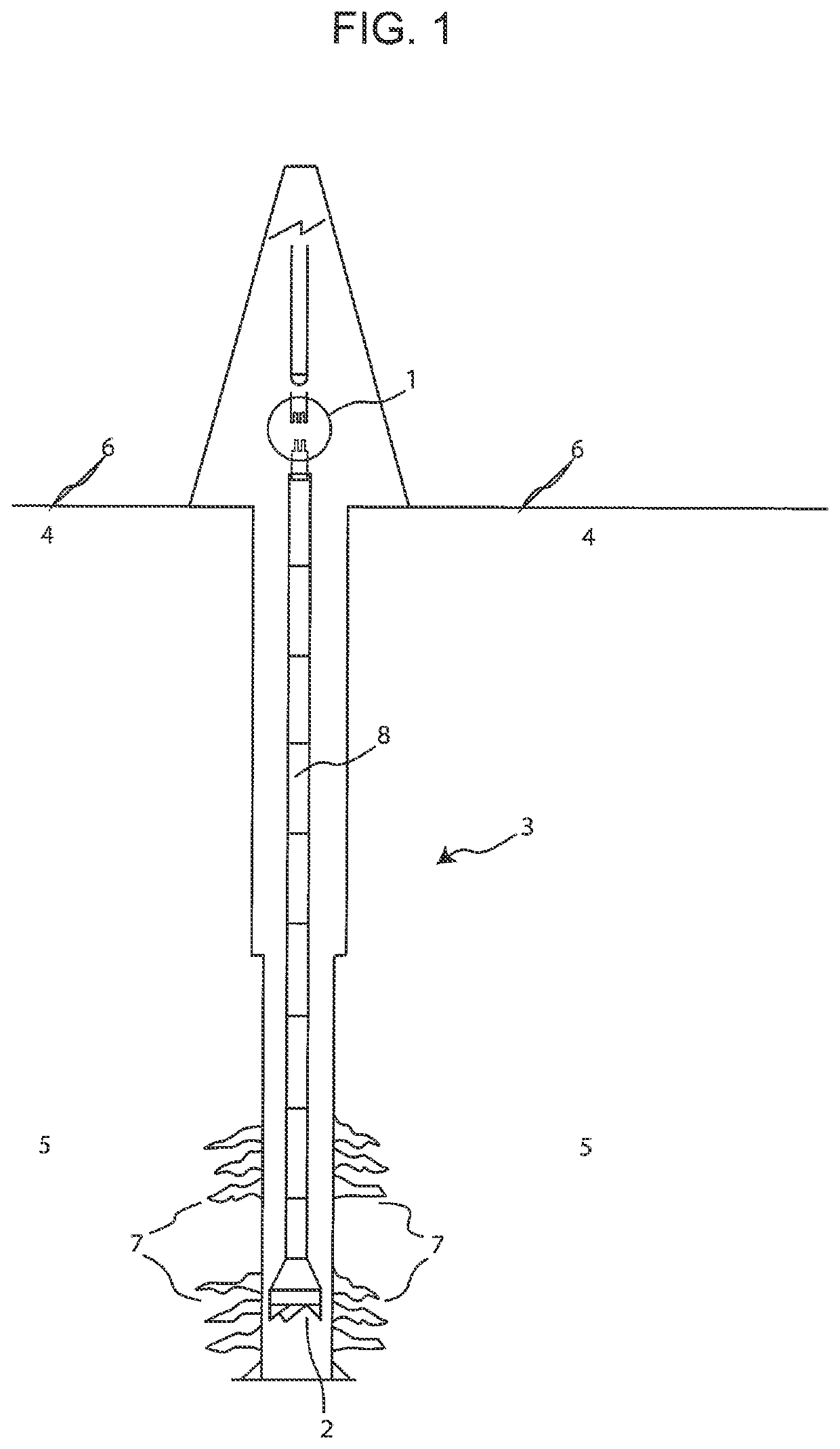
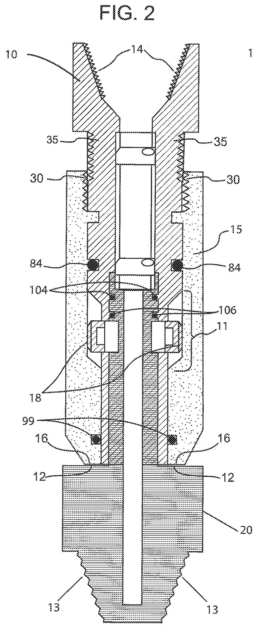
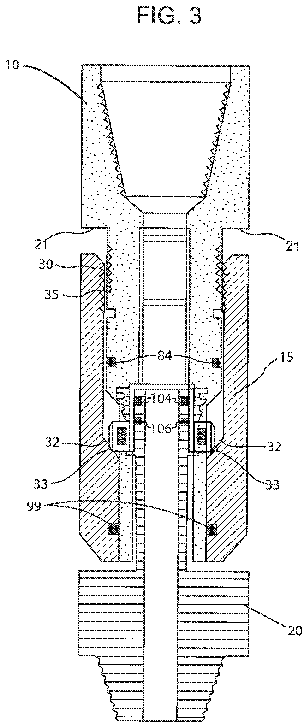
[0052]FIG. 1 illustrates the present invention that is t...


PUM


Abstract

The present invention provides a novel clutch connector assembly for jointed pipe, threaded pipe, coiled tubing or any threaded or non-threaded pipe for a bottom hole assembly that eliminates the need to use screw threads to mate two pipes or mechanical assemblies, harbors a spring-loaded mechanical locking system in addition in to a pressure-activated, component protectant system, requires no significant tools, other than an Allen wrench or similar screw setting device, permits distributed torque loading, allows for movement in either a clockwise or counter clockwise rotational direction through interlocking castellations and presents a removeable and replaceable valve assembly preventing retrograde hydrocarbon advancement through a drilling pipe.

Description

CROSS REFERENCE TO RELATED APPLICATIONS[0001]The present application is a Continuation-in-Part application (CIP) of previously filed U.S. patent application Ser. No. 15 / 330,946 filed Feb. 3, 2015 the entire contents of which are incorporated by reference in their entirety.CROSS-REFERENCE TO RELATED APPLICATIONS[0002]Priority claimed to Non-Provisional U.S. Ser. No. 15 / 330,946 filed Feb. 3, 2015FEDERALLY SPONSORED RESEARCH OR DEVELOPMENT[0003]Not ApplicableINCORPORATION BY REFERENCE OF MATERIAL SUBMITTED ON A COMPACT DISK[0004]Not ApplicableFIELD OF THE INVENTION[0005]The present invention relates generally to the design of a mechanical connection assembly used in conjunction with jointed pipe, threaded pipe, coiled tubing, stick pipe and any other threaded or non-threaded pipe section (or tubular) for downhole operations which involve and utilize inline safety valves (also known in the art as check valves, safety valves, flapper valves and ball valves or valves of similar nature) pe...

Claims


Application Information

Patent Timeline
Patent Type & Authority Patents(United States)
IPC IPC(8): F16L19/00E21B17/043F16L15/08E21B17/04E21B17/046
CPCE21B17/043E21B17/04E21B17/046F16L15/08F16L19/005E21B2200/05
Inventor MCLAUGHLIN, STUART
Owner MCLAUGHLIN STUART
Why Eureka
Try Eureka