
Multilayer Medical Sponge

a multi-layer sponge and sponge technology, applied in the field of medical sponges, can solve the problems of affecting the safety of surgery, and affecting the safety of other medical procedures, so as to achieve the effect of improving the safety of surgery and other medical procedures

Inactive Publication Date: 2011-03-17
SHAO WEIRU
View PDF5 Cites 13 Cited by
  • Summary
  • Abstract
  • Description
  • Claims
  • Application Information

AI Technical Summary

Benefits of technology

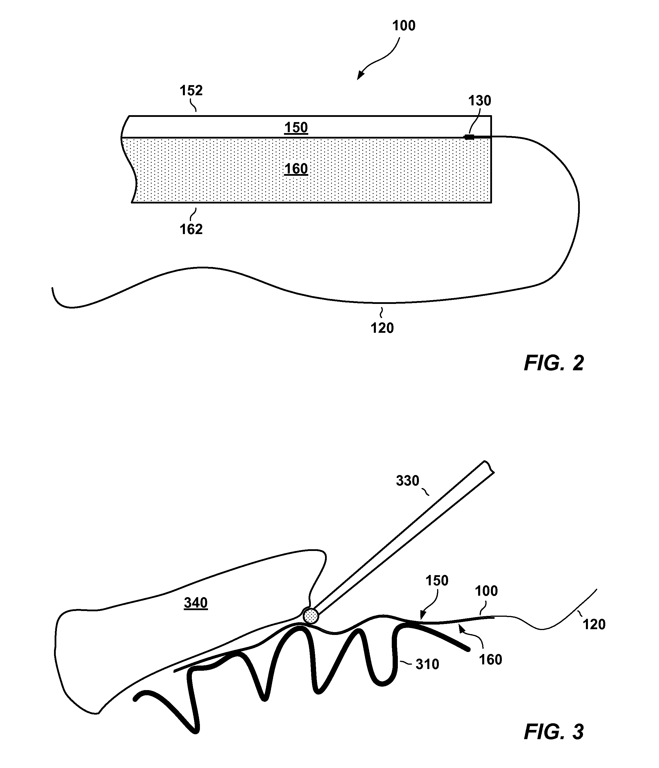
[0013]The inventor has recognized and appreciated that the safety of surgeries and other medical procedures may be improved by a multilayer medical sponge. In accordance with one embodiment, the multilayer medical sponge includes at least two layers, an absorbent layer and a resistant layer. The absorbent layer may be placed against sensitive tissues to cover them and provide hydration during medical procedures, whereas the resistant layer may face away from these tissues to help protect them from damage resulting from various hazards, such as impingement of medical tools, including spinning drill bits or laser light, upon the multilayer sponge.
[0018]In accordance with a still further embodiment, a method of preventing damage with a medical sponge during a medical operation includes providing a medical sponge having a first layer constructed from a biocompatible material adhered to a second layer constructed from a deflection material. The method further includes placing the medical sponge proximate to at least one critical structure of a medical patient and using a medical tool proximate to the at least one critical structure, wherein the second layer of the medical sponge is positioned to substantially deflect the medical tool.

Problems solved by technology

Working space in these surgeries is sometimes limited and may lead to accidental injuries.
For example, a laser aimed at a tumor may misfire and ablate healthy tissue adjacent to the tumor.
Also, a spinning drill bit removing bone may nick adjacent critical soft tissue, causing a potentially serious injury.
For example, laser light may penetrate sponges and damage underlying tissues.
Intraoperative fires may be particularly damaging in procedures for which oxygen is fed to the operative field, such as endoscopic laryngeal, bronchial, and tracheal surgeries.
Spinning drill bits also present a hazard.
In some cases, the sponge may be caused to wrap around the drill bit and form a fast spinning ball of material.
The size and speed of the spinning material may be enough to damage adjacent tissues.

Method used


Image

  • Multilayer Medical Sponge
  • Multilayer Medical Sponge
  • Multilayer Medical Sponge

Examples


Embodiment Construction

[0027]Techniques, including a preferred embodiment of the invention, are described hereinbelow for providing a multilayer medical sponge to help protect medical patients against injuries arising from various hazards such as contact with spinning drill bits and other tools or instruments and / or from impingement with laser light. These techniques may be employed to make a multilayer medical sponge and to use a multilayer medical sponge to improve the safety of medical procedures.

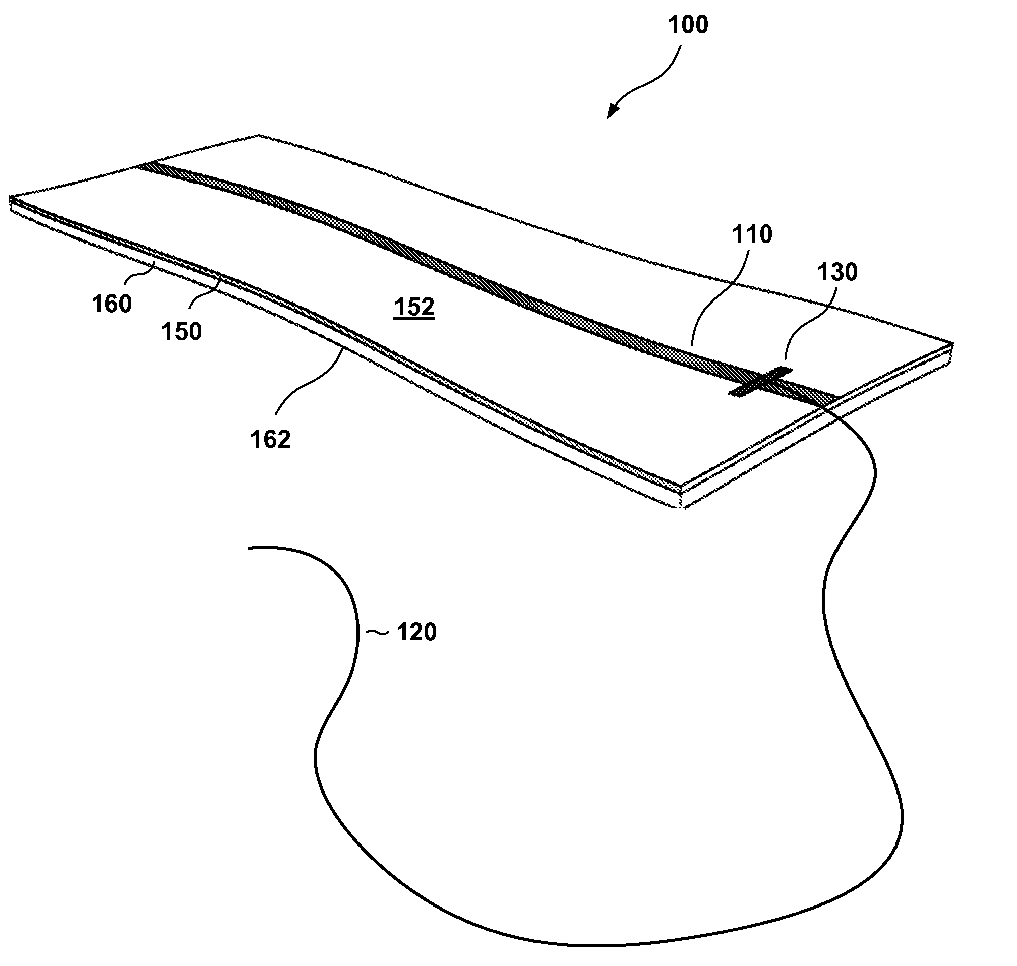
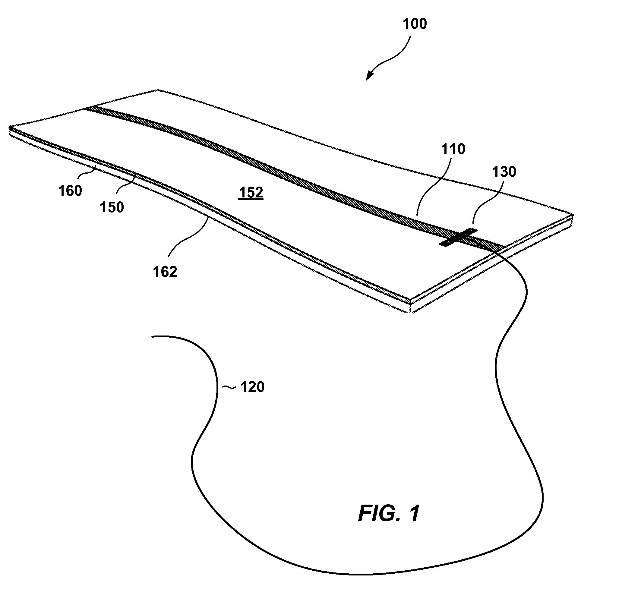
[0028]FIGS. 1 and 2 show an exemplary multilayer medical sponge 100 which provides drill-resistant characteristics. The sponge 100 includes a first layer 160 and a second layer 150. The first layer 160 is made of an absorbent material and has an outward-facing surface 162. The second layer 150 is made of a resistant material and has an outward-facing surface 152. Optionally, a radiopaque marker 110 is applied to the sponge 100 and a string 120 is attached to the sponge using, for example, stitching 130. The ra...


PUM


Abstract

A multilayer medical sponge resists damage from medical tools such as spinning drill bits and medical lasers while remaining compliant and producible in small sizes. The multilayer medical sponge includes an absorbent layer and a resistant layer. The resistant layer may include a drill-resistant material, a laser-reflective material, both types of materials, or a single material that provides both drill-resistant and laser-reflective characteristics.

Description

CROSS-REFERENCES TO RELATED APPLICATIONS[0001]This application claims the benefit of U.S. Provisional Application No. 61 / 394,320 filed Oct. 8, 2010.STATEMENT REGARDING FEDERALLY SPONSORED RESEARCH OR DEVELOPMENT[0002]Not Applicable.NAMES OF PARTIES TO A JOINT RESEARCH AGREEMENT[0003]Not Applicable[0004]REFERENCE TO A “SEQUENCE LISTING,” A TABLE, OR A COMPUTER PROGRAM LISTING APPENDIX[0005]Not Applicable.BACKGROUND OF THE INVENTION[0006]1. Field of the Invention[0007]This invention relates generally to medical sponges and more particularly to medical sponges that are constructed with multiple layers.[0008]2. Description of Related Art[0009]Many medical procedures, including surgeries, are performed with the aid of medical lasers or drills. Frequently, laser ablation or drilling is conducted in close proximity to critical soft tissues, such as brain, blood vessels, and nerves. Working space in these surgeries is sometimes limited and may lead to accidental injuries. For example, a las...

Claims


Application Information

Patent Timeline
IPC IPC(8): A61F13/15
CPCA61F13/00008A61F13/00029A61F13/44A61F13/00063A61F13/00034A61F13/01034A61F13/01029A61F13/01008
Inventor SHAO, WEIRU
Owner SHAO WEIRU
Learn More