Vehicle Control Apparatus

a technology for controlling apparatus and vehicles, applied in brake systems, machines/engines, instruments, etc., can solve problems such as strangeness feeling of drivers, and achieve the effect of reducing the burden of pedal manipulation

Inactive Publication Date: 2011-03-17
HITACHI AUTOMOTIVE SYST LTD
View PDF20 Cites 55 Cited by
  • Summary
  • Abstract
  • Description
  • Claims
  • Application Information

AI Technical Summary

Benefits of technology

[0004]It is an object of the present invention to provide a vehicle control apparatus, devised to

Problems solved by technology

However, since these braking-force values are predetermined values, there is a risk that the driver has a strangeness feeling due to a variation of veh

Method used


Image

  • Vehicle Control Apparatus
  • Vehicle Control Apparatus
  • Vehicle Control Apparatus

Examples


first embodiment

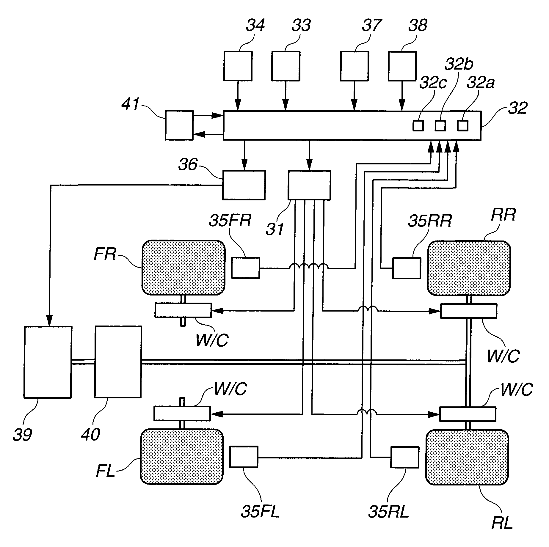
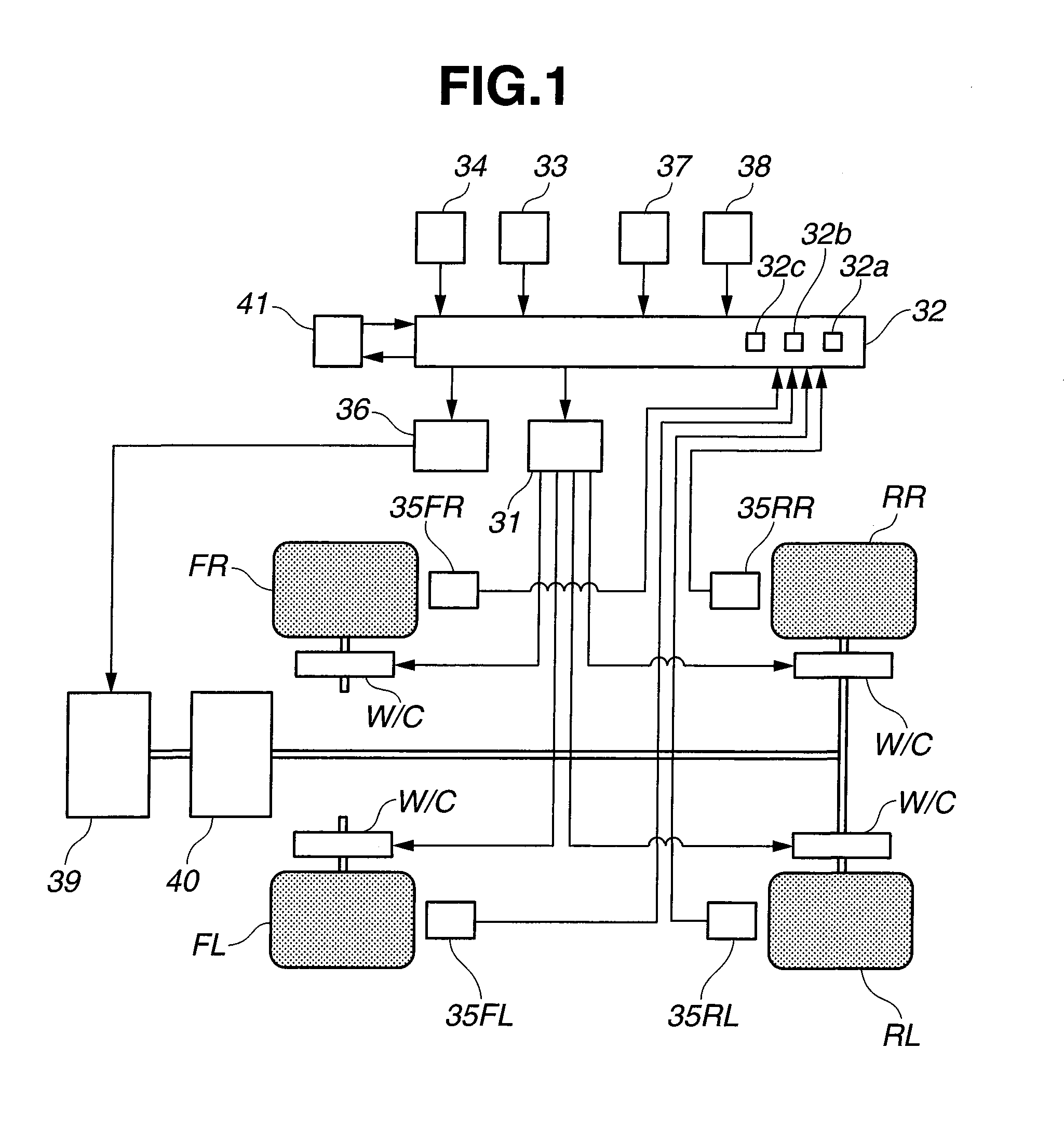
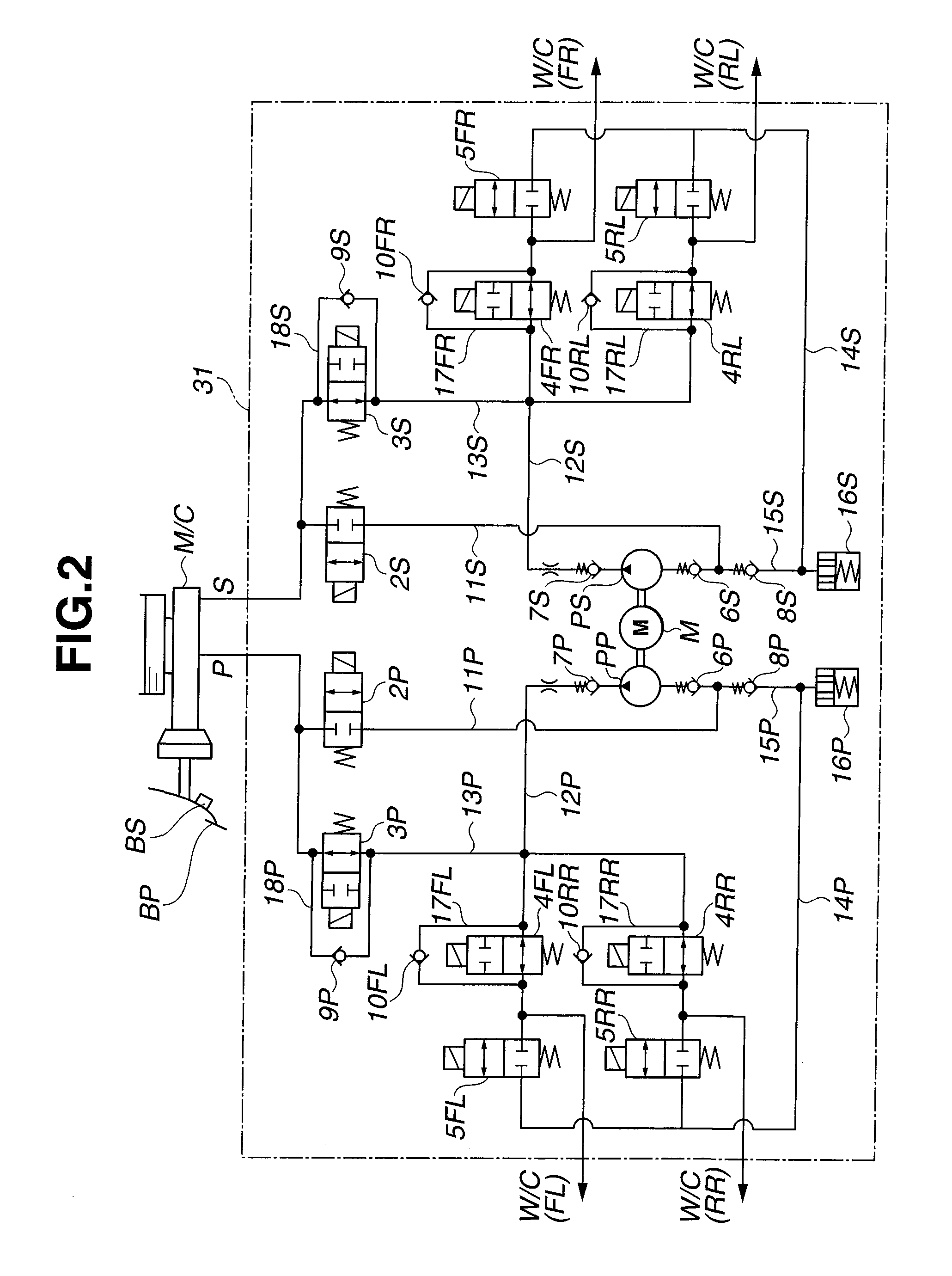
[0021]At first, a configuration according to a first embodiment of the present invention will now be explained. FIG. 1 is a schematic configuration view showing a braking / driving system of vehicle to which a vehicle control apparatus according to the first embodiment has been applied. FIG. 2 is a schematic hydraulic (oil) circuit diagram of a hydraulic unit 31 according to the first embodiment. The vehicle according to the first embodiment includes an engine 39 as its drive source and a transmission 40, and is a vehicle of rear-wheel-drive type. That is, a driving force outputted from the engine 39 is inputted to the transmission 40 for appropriate speed change, and then drives rear right and rear left wheels RR and RL. However, according to the present invention, a front-wheel-drive vehicle or a four-wheel-drive vehicle can also be employed. Moreover, the hydraulic unit 31 is provided to construct a diagonal split layout of brake circuit having two pipe lines of a P-line and an S-l...


PUM


Abstract

A vehicle control apparatus includes an accelerator-manipulated-amount detecting section configured to detect a manipulated amount of accelerator; a braking-force generating section configured to generate a braking force of the vehicle; a driving-force generating section configured to generate a driving force of the vehicle; a control unit including a vehicle-body speed calculating section configured to calculate an actual vehicle-body speed. The control unit is configured to perform a normal control mode which generates a driving force corresponding to the accelerator manipulated amount, and to perform a speed control mode which calculates a target vehicle-body speed based on the accelerator manipulated amount and which controls the braking-force generating section and the driving-force generating section so as to bring the actual vehicle-body speed closer to the target vehicle-body speed. The vehicle control apparatus further includes a selecting switch configured to select between the normal control mode and the speed control mode. The control unit is configured to control the vehicle by one selected between the normal control mode and the speed control mode by the selecting switch.

Description

BACKGROUND OF THE INVENTION[0001]The present invention relates to a vehicle control apparatus for controlling a running state of vehicle.[0002]Previously, at a vehicle running in traffic jam, start, acceleration and stop of the vehicle have been conducted by accelerator and brake manipulations of a driver. Hence, there has been a problem that frequent changeovers between the both manipulations (changeover between brake-pedal depression and accelerator-pedal depression) are burdensome to the driver. Moreover, in a scene where a vehicle runs over a bump such as a step formed at an entrance of parking space when the vehicle is parked, the driver needs to switch between the accelerator manipulation and the brake manipulation more rapidly, resulting in a burden to the driver. Japanese Patent Application Publication No. 10-329684 discloses a previously-proposed technique. In this technique, a predetermined braking force based on a vehicle-body speed and a manipulated amount of accelerator...

Claims


Application Information

Patent Timeline
IPC IPC(8): B60W40/12B60W50/08B60T7/12B60W10/04B60W10/06B60W10/18B60W10/188B60W30/00B60W40/06B60W40/072B60W40/076F02D29/02
CPCB60T7/042B60T7/12B60T13/662B60T13/686B60T2210/12B60W2540/12B60W30/143B60W50/085B60W2520/10B60W2540/10B60T2250/04B60T8/4872B60W2540/18
Inventor OZAKI, KAZUNORI
Owner HITACHI AUTOMOTIVE SYST LTD
Why Eureka
Try Eureka