Fuel cell system and control method

a fuel cell and control method technology, applied in the field of fuel cell systems, can solve the problems of reduced performance in charge and discharge, reduced power supply, and reduced battery life, so as to reduce temperature, low power, and low demand output

Inactive Publication Date: 2006-04-27
NISSAN MOTOR CO LTD
View PDF3 Cites 28 Cited by
  • Summary
  • Abstract
  • Description
  • Claims
  • Application Information

AI Technical Summary

Benefits of technology

[0006] Even in a travel with the stack and battery warmed up, the motor may require low power, demanding the stack to output low power. For the battery also, demanded output may be low. Such demands may maintain in outdoor low of temperature. The stack and/or battery may thus have a gradually lowered temperature, with a commensurate reduction in available output therefrom

Problems solved by technology

However, in probably most situations where the stack has a low temperature condition, the battery may also have a low temperature condition with a reduced performance in charge and discharge.
Stored energy in the battery may thus be limited, with a resultant failure to supply sufficient power to the motor.
For example, in a fuel cell vehicle after complete warm-up, the battery as well as the stack may exper

Method used


Image

  • Fuel cell system and control method
  • Fuel cell system and control method
  • Fuel cell system and control method

Examples


first embodiment

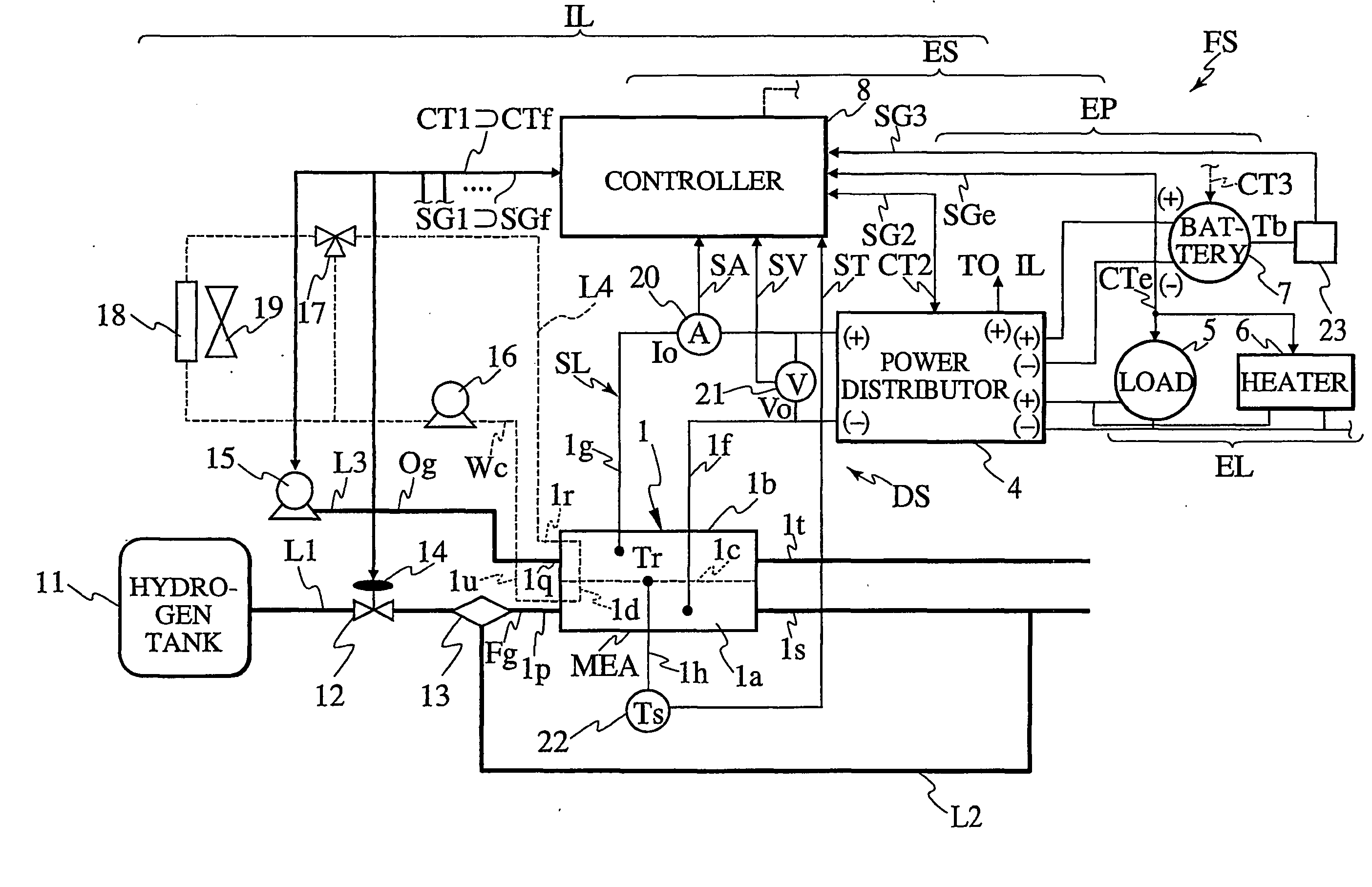
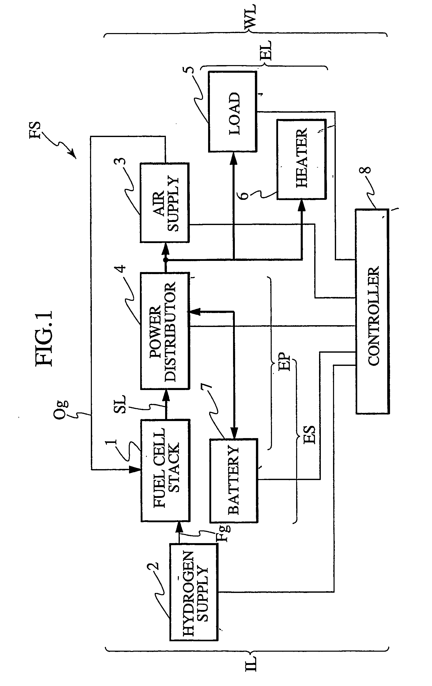
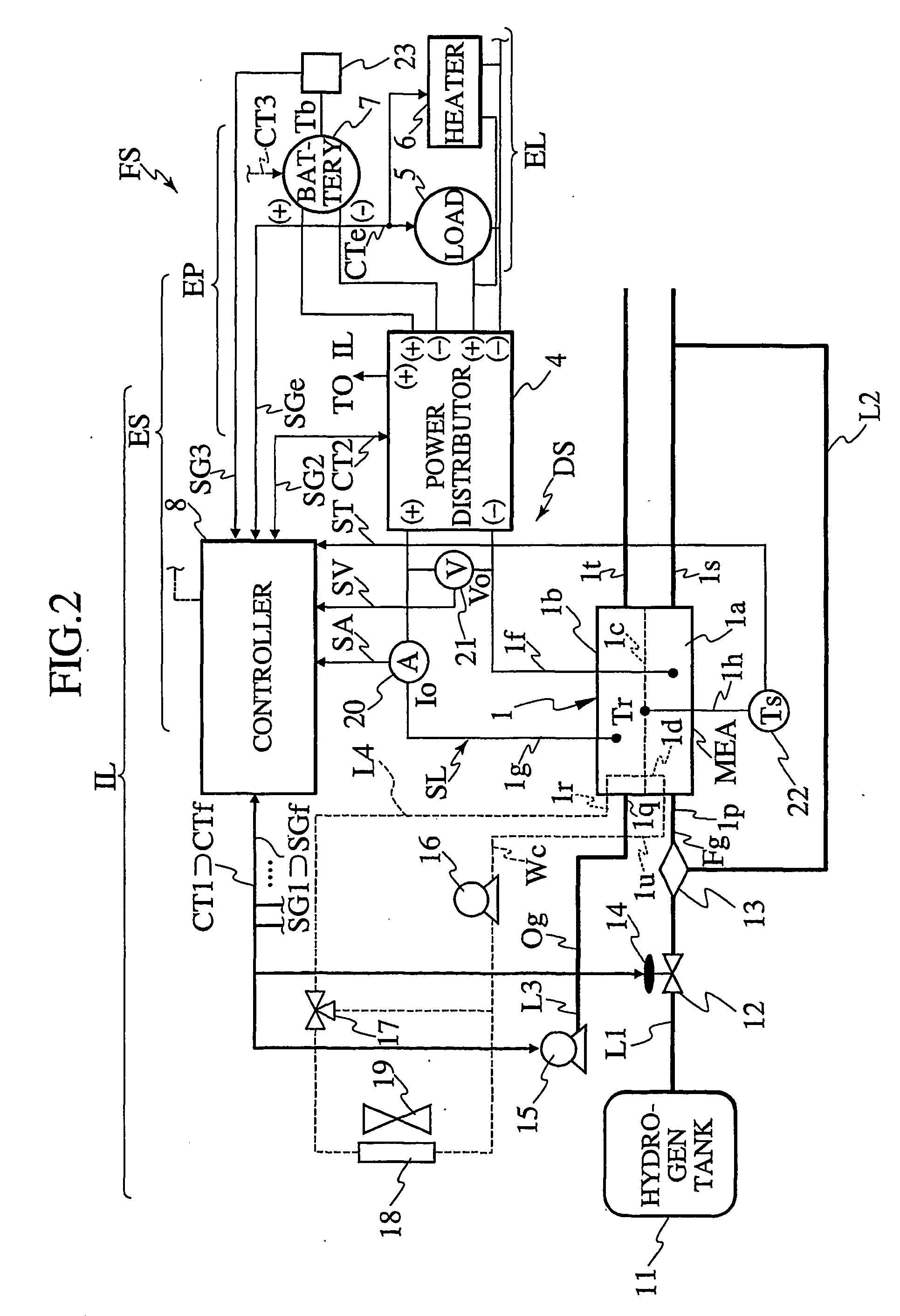
[0019] Description is now made of a fuel cell system FS according to a first embodiment of the invention, as the best mode, with reference to FIGS. 1 to 4, and sometimes to FIG. 5.

[0020] (Fuel Cell System)

[0021]FIG. 1 is a block diagram of the fuel cell system FS, and FIG. 2, a detailed diagram of the same with essential circuits. FIG. 5 is a longitudinal section of a fuel cell vehicle V, on which is mounted a fuel cell system FSr according to a second embodiment of the invention that is configured as a combination of the fuel cell system FS of the first embodiment and a set of later-described additional elements (e.g. battery chamber cooling air fan 72 and air return valve 74).

[0022] The fuel cell system FS has a fuel cell stack 1 (FIGS. 1, 2, 5) as an en electric power supply configured to generate and supply electric power, with a gaseous fuel Fg (FIGS. 1, 2) supplied from a hydrogen supply 2 (FIG. 1) and a gaseous oxidizer Og (FIGS. 1, 2) supplied from an air supply 3 (FIG. 1...

second embodiment

[0132] Description is now made of a fuel cell system FSr according to the second embodiment of the invention, with reference to FIGS. 5 to 7. The fuel cell system FSr is configured as a combination of the fuel cell system FS (FIGS. 1-2) of the first embodiment and additional elements (FIG. 5), as described.

[0133]FIG. 5 shows, in a schematic section, a fuel cell vehicle V having the fuel cell system FSr incorporated therein. FIGS. 6 and 7 describe an associated control process CF3 and a modified control process CF4, each respectively as part of the performance securing normal control CP of the first embodiment.

[0134] (Fuel Cell Vehicle)

[0135] The fuel cell vehicle V is configured with a longitudinal passenger room PR furnished with front and rear sheets ST1 and ST2, a front section having a front chamber C1 and front wheels FW, a lower middle section having a middle front chamber C2 and a middle rear chamber C3 between axles of front and rear wheels FW and RW, and a rear section h...


PUM


Abstract

During a normal control (CP) having a fuel supply (3) supplying a fuel (Fg), an air supply (3) supplying an oxidizer (Og), a stack (1) of fuel cells generating power with the fuel and the oxidizer supplied, a battery (7) as a secondary cell operable for power charge and discharge, and a power distributor (4) distributing power from the stack to a main load (5) and operable for distribution of power from the stack to the battery and from the battery to the load, after a startup with the stack and the battery warmed-up, a controller (8) serves for raising a temperature (Ts) of the stack when a possible generation (Gp) of power is reduced and for raising a temperature (Tb) of the battery when a possible charge (Cp) of power or a possible discharge (Dp) of power is reduced, to maintain stable power supply to the load even under a continued low-output condition.

Description

TECHNICAL FIELD [0001] The present invention relates to a fuel cell system and an associated control method, and particularly, to a fuel cell system to be mounted in a vehicle (e.g. fuel cell automobile or train), for power supply to a set of electrical loads including a vehicular drive motor and a fuel cell stack's peripherals, and an associated control method. BACKGROUND ART [0002] Japanese Patent Application Laying-Open Publication No. 9-231991 has disclosed techniques for a fuel cell system to normally supply power to a set of electrical loads including a drive motor and stack peripherals. [0003] To cope with a demand for excessive power on a fuel cell stack under a low temperature condition that merely allows generation of reduced power, the fuel cell system is adapted to supply power of a charged battery (secondary cell) to the motor, controlling the stack for low-output generation to supply power therefrom simply to the peripherals and minor loads drivable by low currents. DI...

Claims


Application Information

Patent Timeline
IPC IPC(8): H01M16/00H01M8/04H01M8/00H01M10/48
CPCH01M8/04007H01M8/04097H01M8/04104H01M8/04298H01M8/04559H01M8/04731H01M8/0494H01M10/486H01M10/5006H01M10/5016H01M10/5022H01M10/5067H01M10/5095H01M16/003H01M2250/20Y02T90/32Y02E60/50H01M10/625H01M10/615H01M10/633H01M10/663H01M10/6563Y02T90/40Y02E60/10H01M8/04
Inventor ASO, TAKESHI
Owner NISSAN MOTOR CO LTD
Why Eureka
Try Eureka