Electric power steering system

a technology of steering wheel and electric motor, which is applied in the direction of steering initiation, vessel parts, instruments, etc., can solve the problems of increasing the number of parts, the inability to supply power to the motor and assist the steering wheel operation, and the increase of the manufacturing cos

Active Publication Date: 2013-04-11
DENSO CORP
View PDF0 Cites 31 Cited by
  • Summary
  • Abstract
  • Description
  • Claims
  • Application Information

AI Technical Summary

Benefits of technology

[0012]In the control unit, the state detection section detects that the control unit is in a normal control operation state for controlling the power supply to the motor by controlling the first motor drive circuit and the second motor drive circuit after an ignition switch is turned on. The failure diagnosis section diagnoses alternately a short-circuit failure of the first power shut-off circuit and the second power shut-off circuit, when the state detection section detects that the control unit is in the normal co

Problems solved by technology

According to the EPS of patent document 1, however, when the failure diagnosis for the power relay or the motor relay is performed in the normal control operation, it becomes impossible to suppl

Method used


Image

  • Electric power steering system
  • Electric power steering system
  • Electric power steering system

Examples


first embodiment

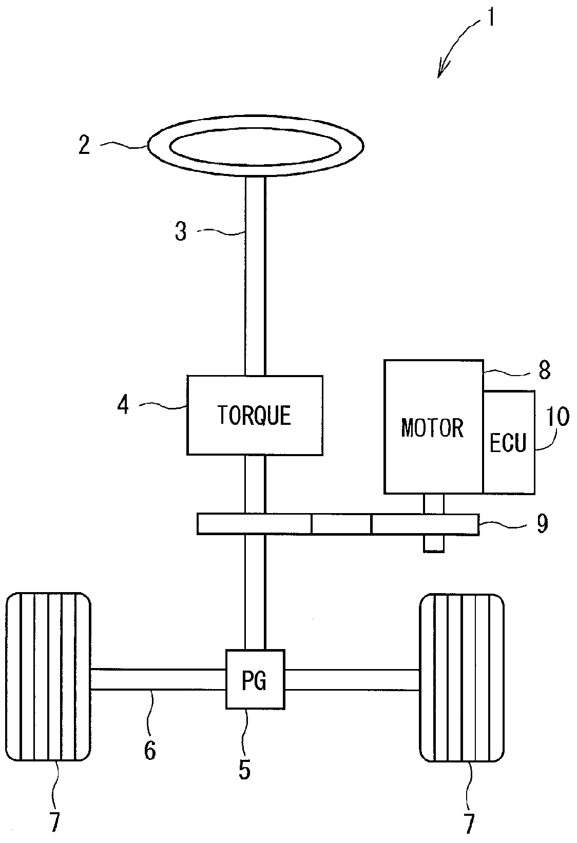
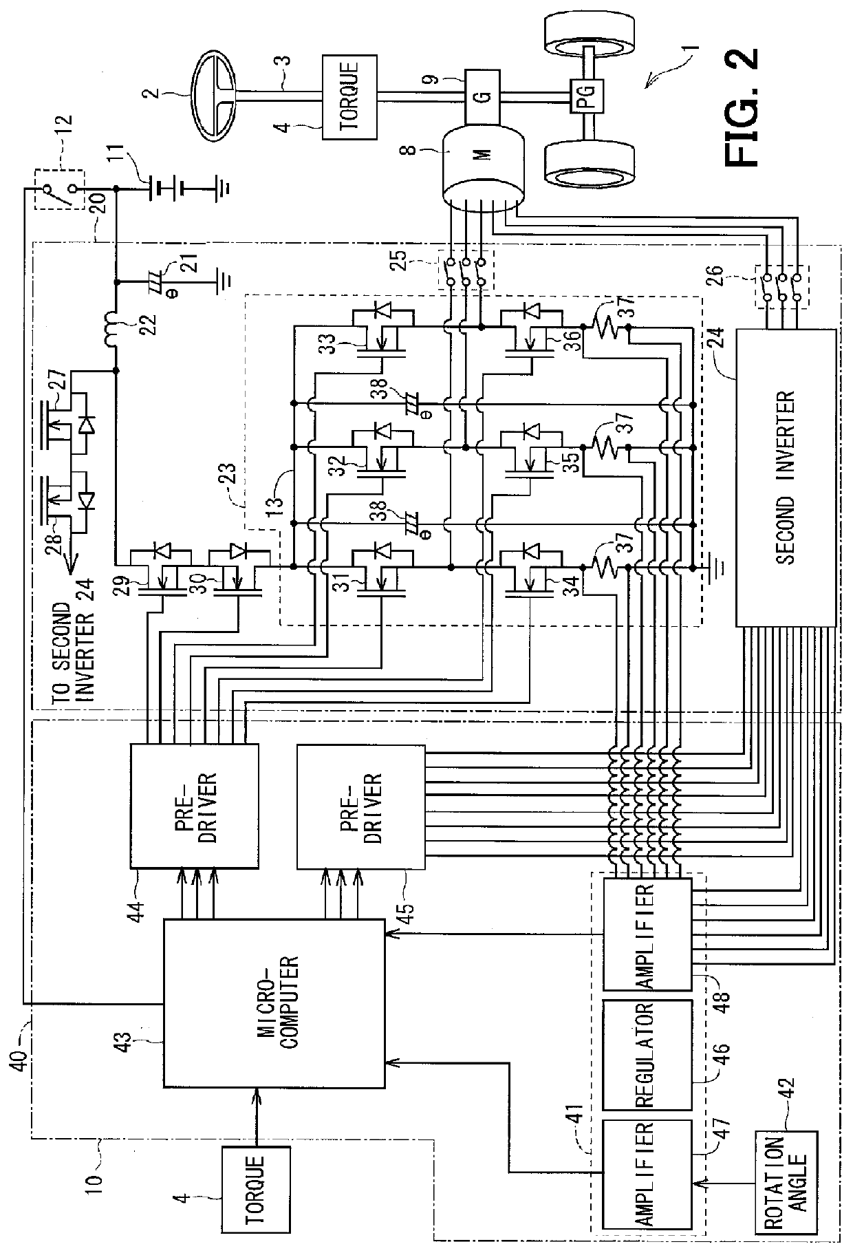
[0019]Referring to FIG. 1, an electric power steering system (EPS) 1 is provided in a vehicle, which has a steering wheel 2, a steering shaft 3, a pinion gear 5, a rack shaft 6 and a pair of tire wheels 7. A torque sensor 4 is attached to the steering shaft 3 coupled to the steering wheel 2 for detecting a steering torque. At a top end of the steering shaft 3, the pinion gear 5 is provided. The pinion gear 5 is meshed with the rack shaft 6. At both ends of the rack shaft 6, the tire wheels 7 are rotatably coupled through tie rods and the like. Thus the rotary motion of the steering shaft 3 is converted to the linear motion of the rack shaft 6 by the pinion gear 5. The tire wheels 7 are steered by an angle corresponding to a linear movement of the rack shaft 6. The EPS 1 is formed of an electric motor 8, a reduction gear 9 and an electronic control unit (ECU) 10, which controls driving of the motor 8. The motor 8 is a three-phase brushless motor and generates assist torque for power-...

second embodiment

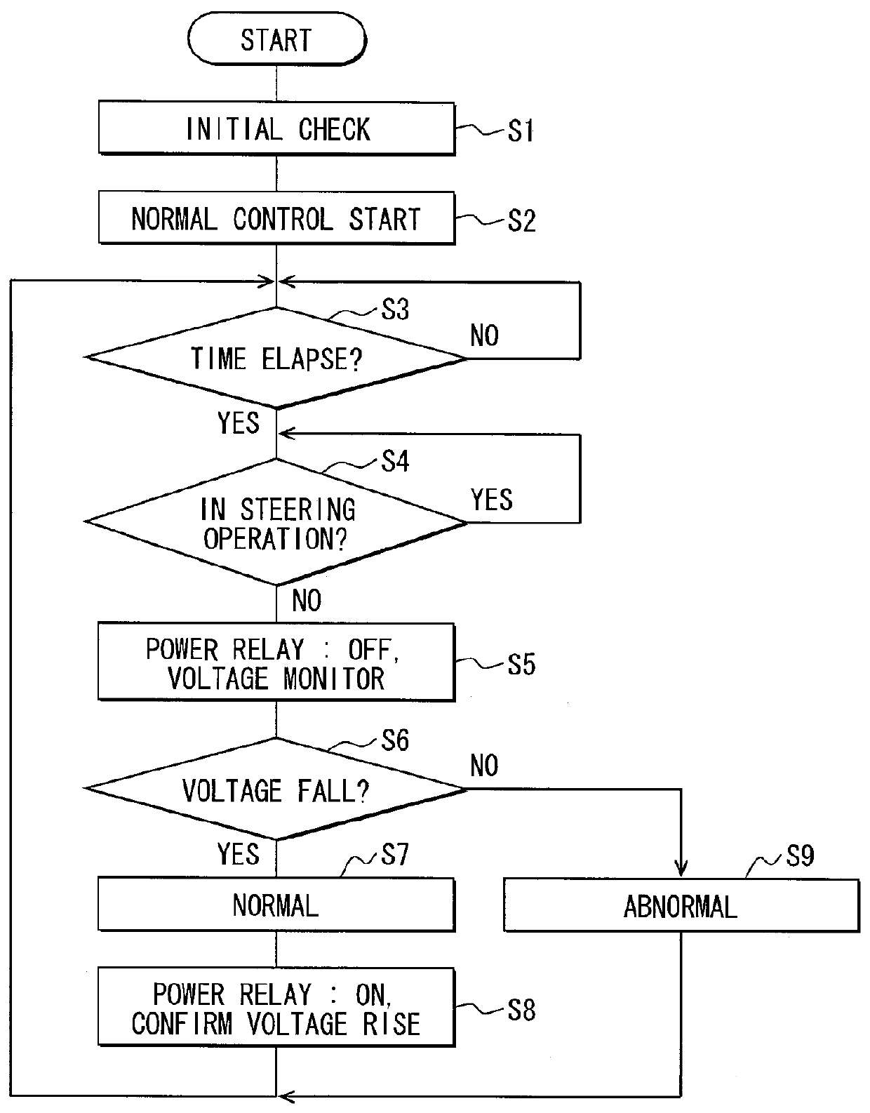
[0040]A failure diagnosis operation performed by an EPS according to a second embodiment will be described with reference to a flowchart shown in FIG. 4. In the second embodiment, the same or similar parts as in the first embodiment are designated by the same or similar reference numerals to simplify the description.

[0041]According to the second embodiment, the power relays 29, 30 and the inverter circuit 23, which are provided in the first power module, are referred to as the first power relays 29, 30 and the first inverter circuit 23, respectively. The power relays 27, 28 and the inverter circuit 24, which are provided in the second power module, are referred to as the second power relays 27, 28 and the second inverter circuit 24, respectively.

[0042]S1 to S3 are the same as in the first embodiment. When a predetermined time elapses after the microcomputer 43 started the power supply control (S3: YES), failure diagnosis processing is started. In the failure diagnosis processing, fi...


PUM


Abstract

A power relay is provided in a power line, which supplies power from a power source to a motor through an inverter circuit, to shut off power supply from the power source to the inverter circuit when an abnormality arises. A microcomputer diagnoses a short-circuit failure of the power relay when a steering wheel is not steered during a normal control operation of assisting the steering operation of the steering wheel. An EPS shuts off power supply by the power relay when the steering wheel is not steered, so that the short-circuit failure of the power relay is diagnosed without affecting the assist operation for the steering wheel.

Description

CROSS REFERENCE TO RELATED APPLICATION[0001]This application relates to and incorporates herein by reference Japanese patent application No. 2011-220826 filed on Oct. 5, 2011.TECHNICAL FIELD[0002]The present disclosure relates to an electric power steering system for a vehicle.BACKGROUND ART[0003]A conventional electric power steering system (EPS) assists a steering operation of a steering wheel in a vehicle by drive force of a motor as disclosed in the following patent documents.[0004][Patent document 1] JP 2003-182598A[0005][Patent document 2] JP 2009-248885A[0006]In the EPS disclosed in patent document 1, a failure diagnosis is performed to check whether a power relay, a motor relay and a motor drive circuit are operable normally before starting a normal control operation for assisting a steering operation of a steering wheel in a vehicle after an ignition switch is turned on. In the EPS disclosed in patent document 2, a diagnosis is performed to check whether a power relay has a...

Claims


Application Information

Patent Timeline
IPC IPC(8): G01M17/06B62D6/08B62D5/04
CPCB62D5/0481
Inventor KURODA, YOSHIHIDE
Owner DENSO CORP
Why Eureka
Try Eureka