Vertical Hydroponics System

a hydroponics and vertical technology, applied in valve housings, manufacturing tools, mechanical equipment, etc., can solve the problems of reducing the yield of plaints, ponding and waterlogging, and difficulty in building a channel base that is sufficiently true to enable nutrient films

a hydroponics and vertical technology, applied in valve housings, manufacturing tools, mechanical equipment, etc., can solve the problems of reducing the yield of plaints, ponding and waterlogging, and difficulty in building a channel base that is sufficiently true to enable nutrient films

US20110067301A1Inactive Publication Date: 2011-03-24DEMITCHELL MARK +1

Image

  • Vertical Hydroponics System
  • Vertical Hydroponics System
  • Vertical Hydroponics System

Examples


Embodiment Construction

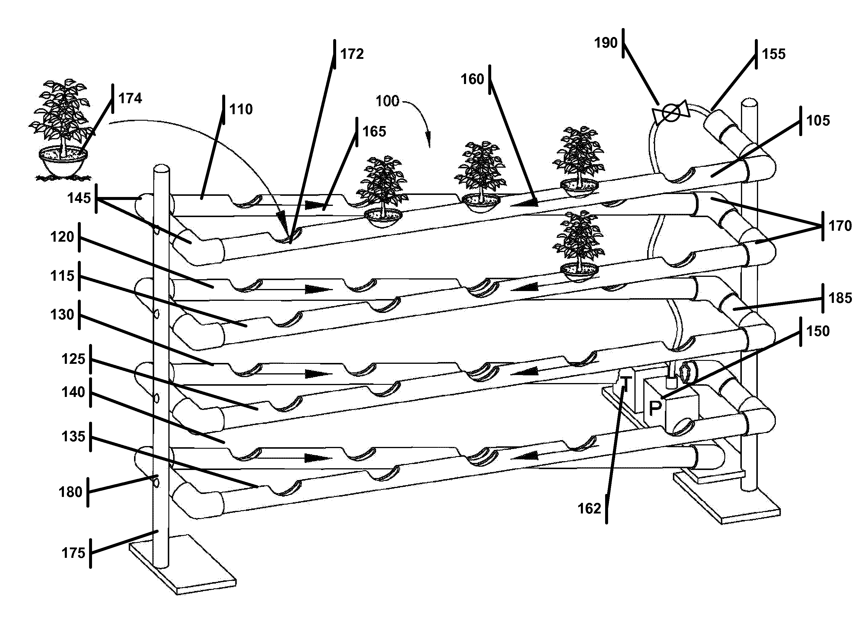
[0018]This disclosure involves a new vertical hydroponics system that implements a very efficient NFT to increase the plant yield over previous vertical system. Also, the system is constructed of very common materials that can be purchased at your local hardware store, thus reducing the costs for maintenance and construction.

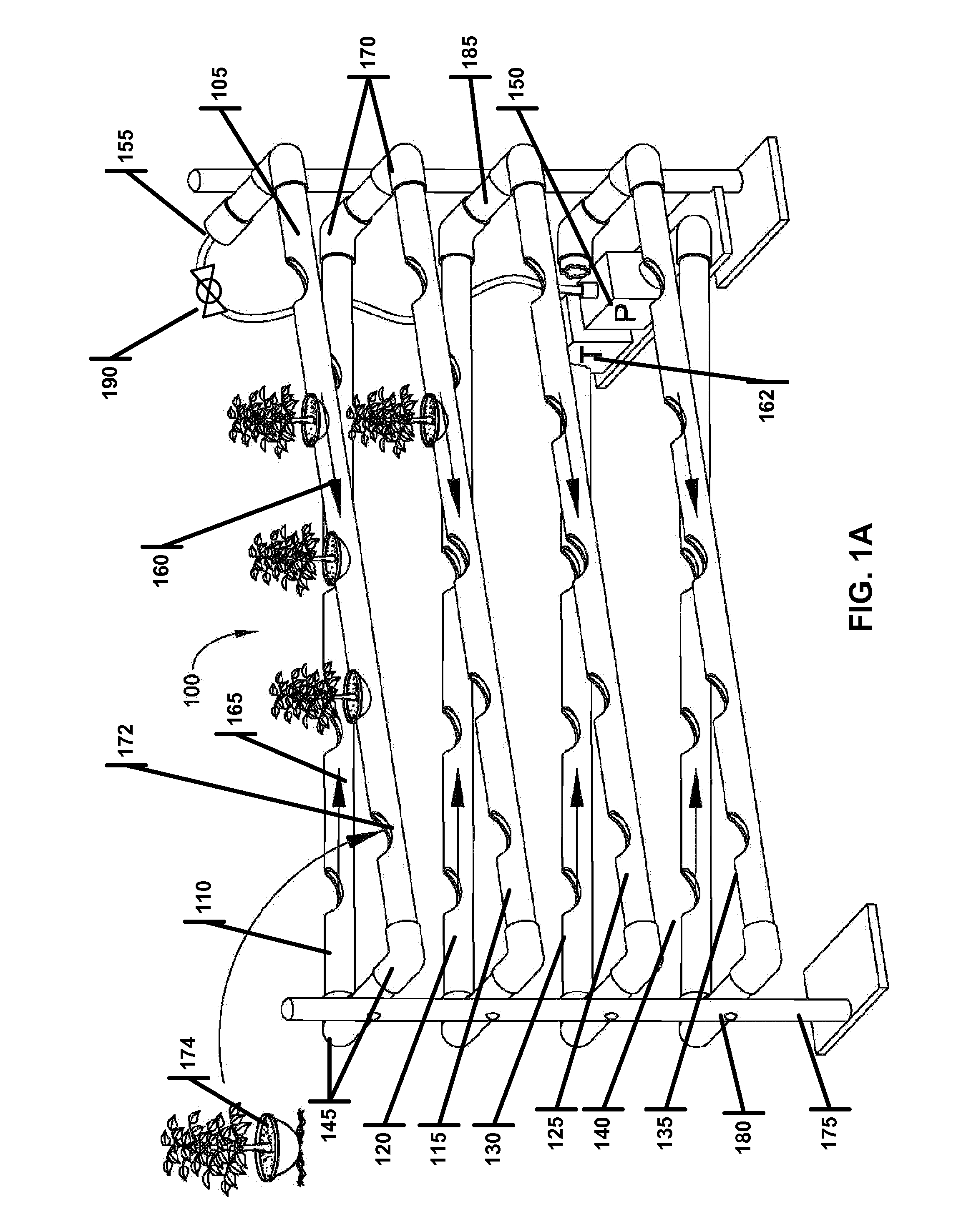
[0019]FIG. 1A illustrates the novel vertical hydroponics system (100). The system may be constructed of a PVC tube of approximately 4 inches in diameter along with several common elbow joints. While the elbow joints shown in FIG. 1A are 90° , the elbow joints could be of various angles. Finally, the system may also include a timer that controls a pump, which can deliver the nutrient rich solution to the plant. The embodiment shown in FIG. 1A, comprises eight inclined horizontal members (105, 110, 115, 120, 125, 130, 135, 140) comprised of PVC pipe connected to each other by a series of 90° elbows (e.g., 145). Nutrient rich solution is pumped from the pump (150) ...


PUM

PropertyMeasurementUnit
diameteraaaaaaaaaa
anglesaaaaaaaaaa
diameteraaaaaaaaaa

Abstract

A hydroponic system useful for providing a continuous flow nutrient solution to the roots of a plurality of plants. The system includes a tubular assembly of horizontally inclined members interconnected to each other at elbow joints, and comprising a plurality of cutouts configured to receive the roots of the plurality of plants, and having a top entry and a bottom exit. A pump is configured to pump the nutrient solution to the top entry of the tubular assembly, wherein the angles of the horizontally inclined members allow the solution to flow downward through the tubular assembly before exiting through the bottom to return to the pump.

Description

1.0 BACKGROUND[0001]The two chief merits of the hydroponics are, first, much higher crop yields, and second, the fact that hydroponics can be used in places where ordinary agriculture or gardening is impossible. People living in crowded city streets, without gardens, can grow fresh vegetables and fruits in window-boxes or on house tops. By means of hydroponics all such places can be made to yield a regular and abundant supply of clean, health-giving greens. Other advantages include faster growth combined with relative freedom from soil diseases, and very consistent crops, the quality of produce being excellent. There is also a considerable reduction in growing area, weeds are practically non-existent, while automatic operation results in less labor, cost, and maintenance.[0002]There are primarily two types of hydroponics systems: static solution culture and continuous flow solution culture. In static solution culture, plants are grown in containers of nutrient solution. The nutrient...

Claims


Application Information

Patent Timeline
24 Mar 2011
Publication
US20110067301A1
IPC
A01G31/02; F16K27/00
CPC
A01G2031/006; A01G31/02; Y02P60/21
Inventors
DEMITCHELL, MARK; TARZIAN, MICHAEL