Vehicle exhaust heat recovery system and method of managing exhaust heat

a technology for exhaust heat recovery and vehicles, applied in indirect heat exchangers, machines/engines, lighting and heating apparatus, etc., can solve problems such as affecting fuel economy and especially difficult engine warm-up, and achieve the effect of improving transmission durability and fuel economy

Inactive Publication Date: 2011-03-24
GM GLOBAL TECH OPERATIONS LLC
View PDF10 Cites 28 Cited by
  • Summary
  • Abstract
  • Description
  • Claims
  • Application Information

AI Technical Summary

Benefits of technology

[0009]Still further, the valve controllable to permit exhaust heat flow to the transmission heat exchanger (referred to as the transmission valve) may be positioned to permit fluid communication between the engine and the transmission heat exchanger if the engine load is above a predetermined threshold engine load, engine speed is above a predetermined threshold engine speed, and/or transmission temperature is above a predetermined maximum transmission temperature. The fluid thus communicated does not pass through the exhaust heat recovery device betwee...

Problems solved by technology

Engine warm-up is especially challenging for diesel and hybrid applications, as less fuel is bur...

Method used


Image

  • Vehicle exhaust heat recovery system and method of managing exhaust heat
  • Vehicle exhaust heat recovery system and method of managing exhaust heat
  • Vehicle exhaust heat recovery system and method of managing exhaust heat

Examples


Embodiment Construction

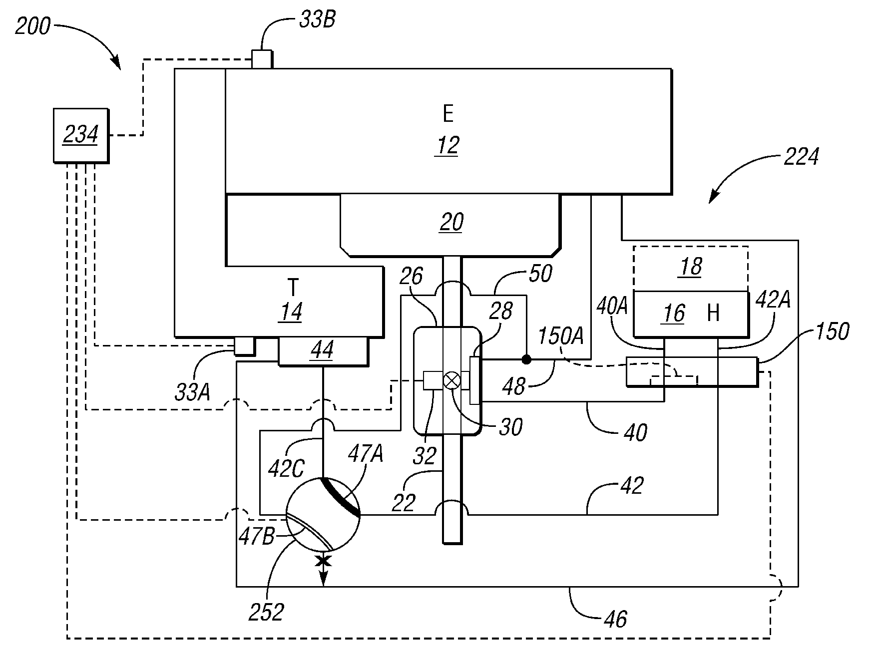
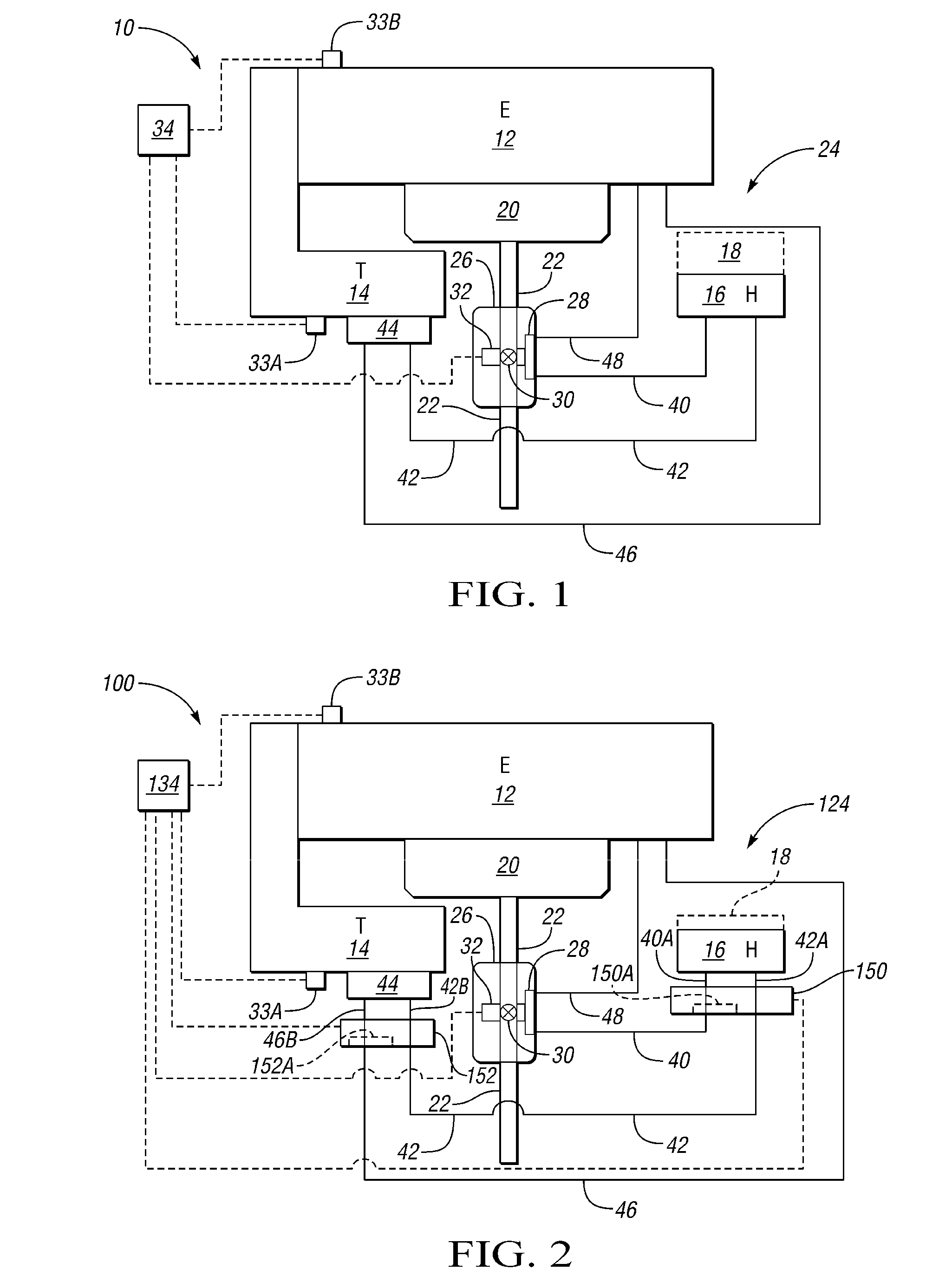
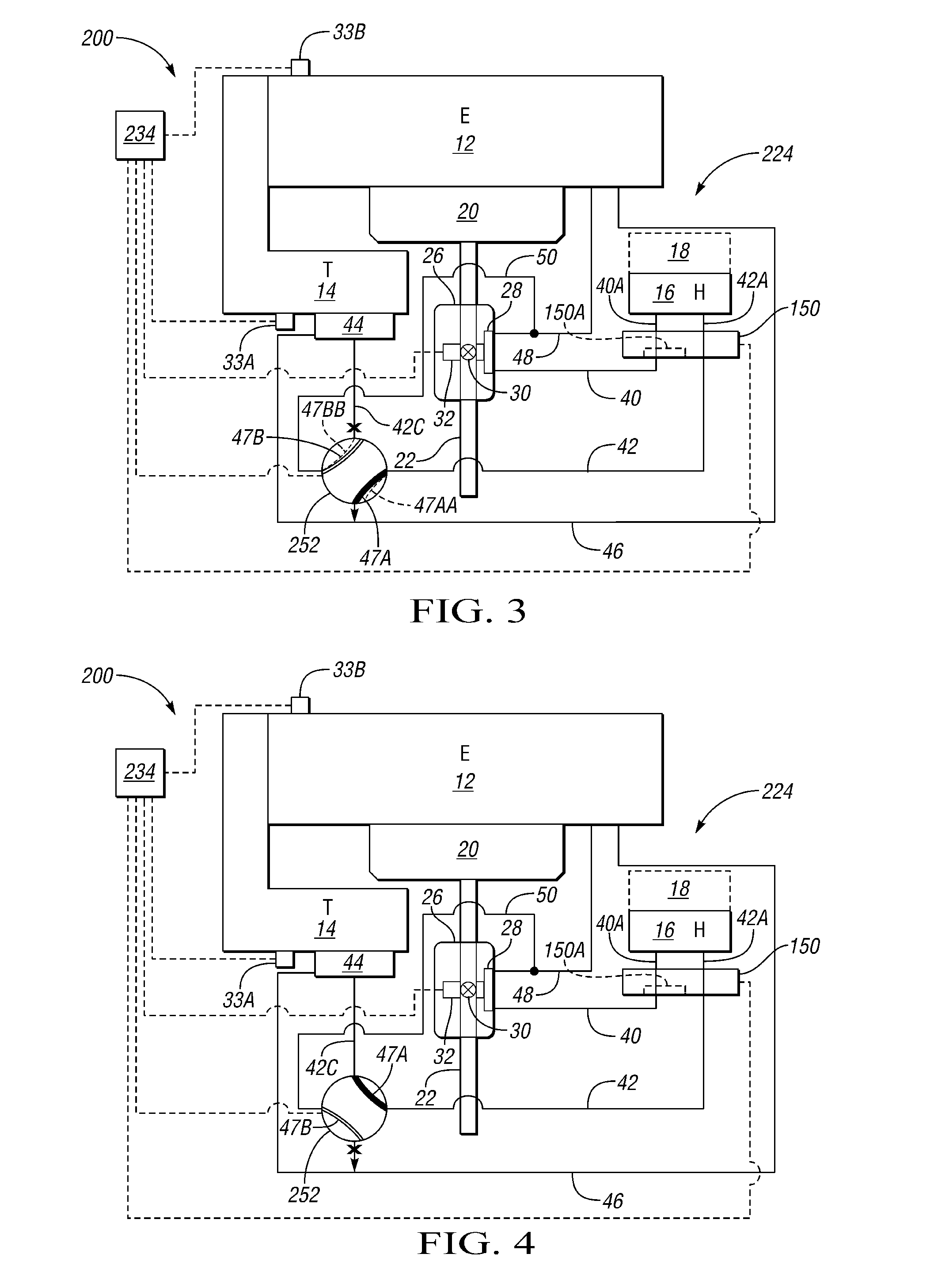
[0016]Referring to the drawings, wherein like reference numbers refer to like components throughout the several views, FIG. 1 shows a vehicle 10 that has an engine 12 (labeled E) for propelling the vehicle 10, a transmission 14 (labeled T) operatively connected to the engine 12, and a passenger compartment heater 16 (labeled H) for heating a passenger compartment, indicated in phantom as 18.

[0017]The engine 10 is an internal combustion engine of the gasoline or diesel type, and generates exhaust gas in an exhaust system that includes an exhaust manifold 20 and an exhaust pipe 22 extending therefrom. The exhaust gas, which is relatively hot, exits the vehicle via the exhaust pipe 22. An exhaust heat recovery system (EHRS) 24 is provided in order to selectively capture some of the exhaust heat for providing heat to the passenger compartment 16, the transmission 14, and the engine 12. The EHRS 24 includes an exhaust heat recovery device (EHRD) 26 positioned in the exhaust system. Speci...


PUM


Abstract

An exhaust heat recovery system (EHRS) for a vehicle is operable to direct exhaust heat to a vehicle transmission under certain operating conditions. In some embodiments, the EHRS may also direct exhaust heat to a heater for vehicle passenger compartment. Preferably, the EHRS is controllable to manage available exhaust heat according to vehicle operating conditions, by prioritizing the heat flow among the engine, the transmission, and the vehicle heater. The EHRS may also operate in a bypass mode during which exhaust heat is not directed to the engine, the transmission or the vehicle heater. A method of managing exhaust heat recovery on a vehicle having an EHRS is also provided.

Description

TECHNICAL FIELD[0001]The invention relates to an exhaust heat recovery system for a vehicle, and a method of managing exhaust heat.BACKGROUND OF THE INVENTION[0002]Rapid warm-up of engine fluid, engine oil, and transmission fluid is important to fuel economy during a cold start (i.e., when the vehicle has not been running and the engine and transmission are relatively cold). Engine warm-up is especially challenging for diesel and hybrid applications, as less fuel is burned. Adequate passenger compartment heater performance is also necessary for passenger comfort. Powering the heater using a motor / generator on a hybrid vehicle can negatively impact fuel economy.SUMMARY OF THE INVENTION[0003]An exhaust heat recovery system (EHRS) for a vehicle is provided that is operable to direct exhaust heat to a vehicle transmission under certain operating conditions. In some embodiments, the EHRS may also direct exhaust heat to a heater for vehicle passenger compartment. Preferably, the EHRS is c...

Claims


Application Information

Patent Timeline
IPC IPC(8): F01N5/02F28D7/00F28F27/00
CPCB60H1/025Y02T10/16F01N5/02Y02T10/12
Inventor PRIOR, GREGORY P.CLAYPOLE, GEORGE M.
Owner GM GLOBAL TECH OPERATIONS LLC
Why Eureka
Try Eureka