Geothermal power system

a power system and geothermal technology, applied in the field of geothermal systems, can solve the problems of increasing the capital and operating costs of the geothermal system, contaminating the environment with undesirable or toxic gases, and avoiding the problem of workable system

Inactive Publication Date: 2011-03-24
7238703 CANADA
View PDF11 Cites 20 Cited by
  • Summary
  • Abstract
  • Description
  • Claims
  • Application Information

AI Technical Summary

Benefits of technology

[0003]The invention provides a geothermal system having closed loop circulation, in which the working fluid media circulating in the system, e.g. water and steam, are always separated from any direct contact with the base rock. The hot water or steam brought up to or near the ground surface is therefore free of base rock contaminants, avoiding the need to clean it. The geothermal system of the invention has a single wellbore, sealed from the surrounding rock by a casing. Water (or other liquid or gaseous working medium) is fed into the piping installed in the borehole to be heated and hot water or steam is returned to the surface for use, all within a closed circulation system whereby the water and steam are kept out of all direct contact with the base rock.

Problems solved by technology

Because the water and steam are in direct contact with the base rock, they generally become contaminated with undesirable or toxic gases and chemicals, including hydrogen sulfide, mercury and arsenic.
This increases the capital and operating costs of the geothermal system.
Although the contamination problem has been recognized in the prior art, e.g. U.S. Pat. No. 6,301,894 Halff, a workable system which avoids the problem has not been previously achieved.

Method used


Image

  • Geothermal power system
  • Geothermal power system
  • Geothermal power system

Examples


Embodiment Construction

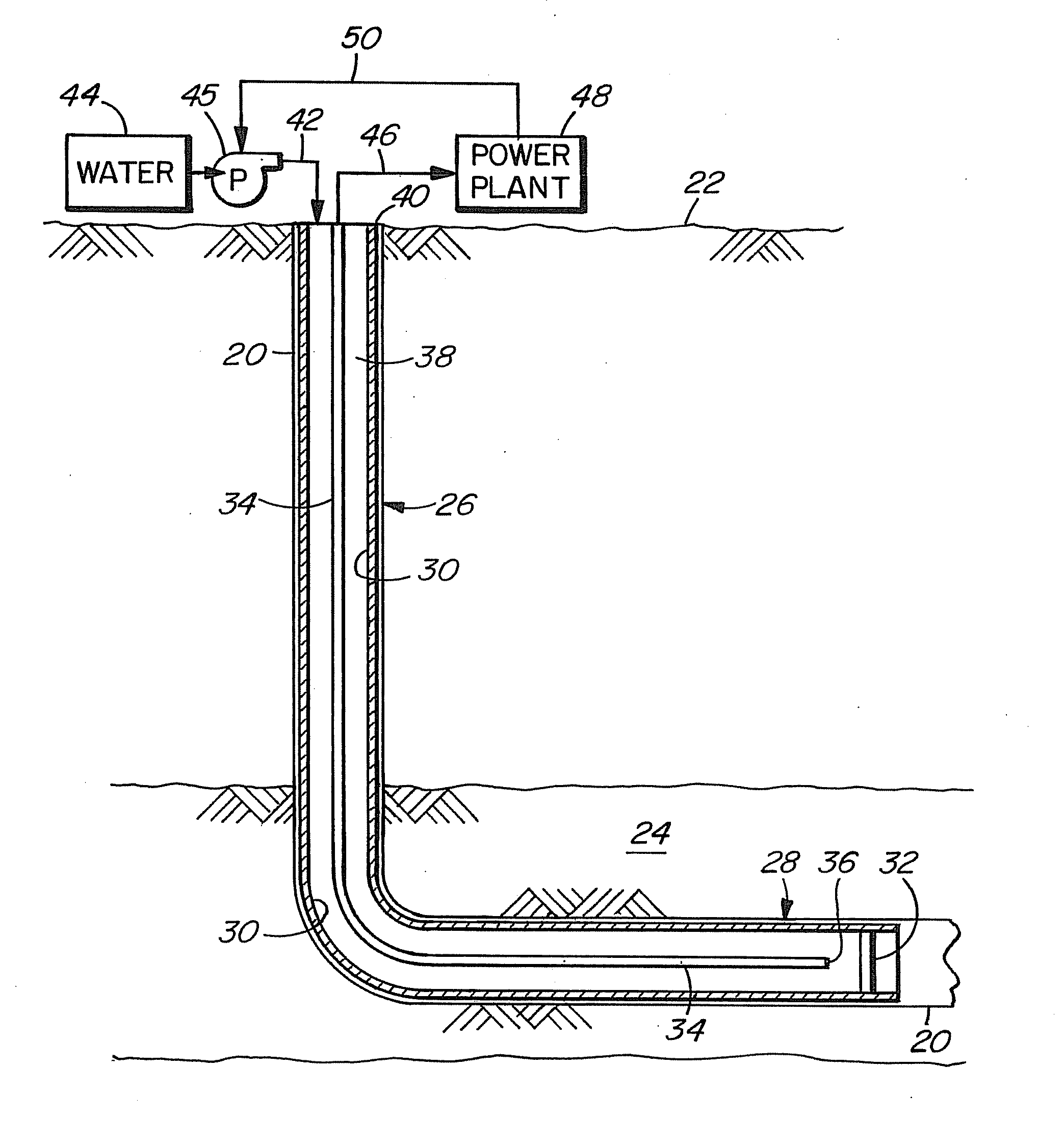
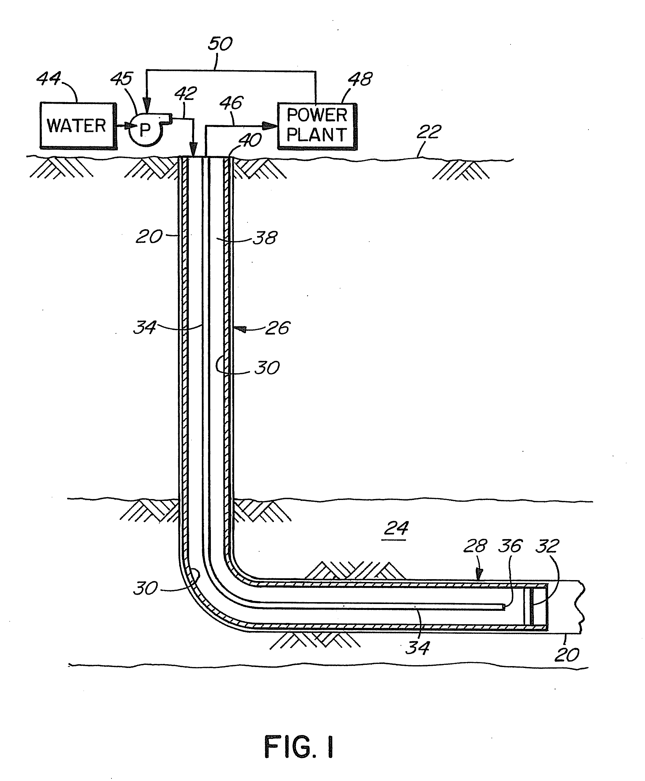
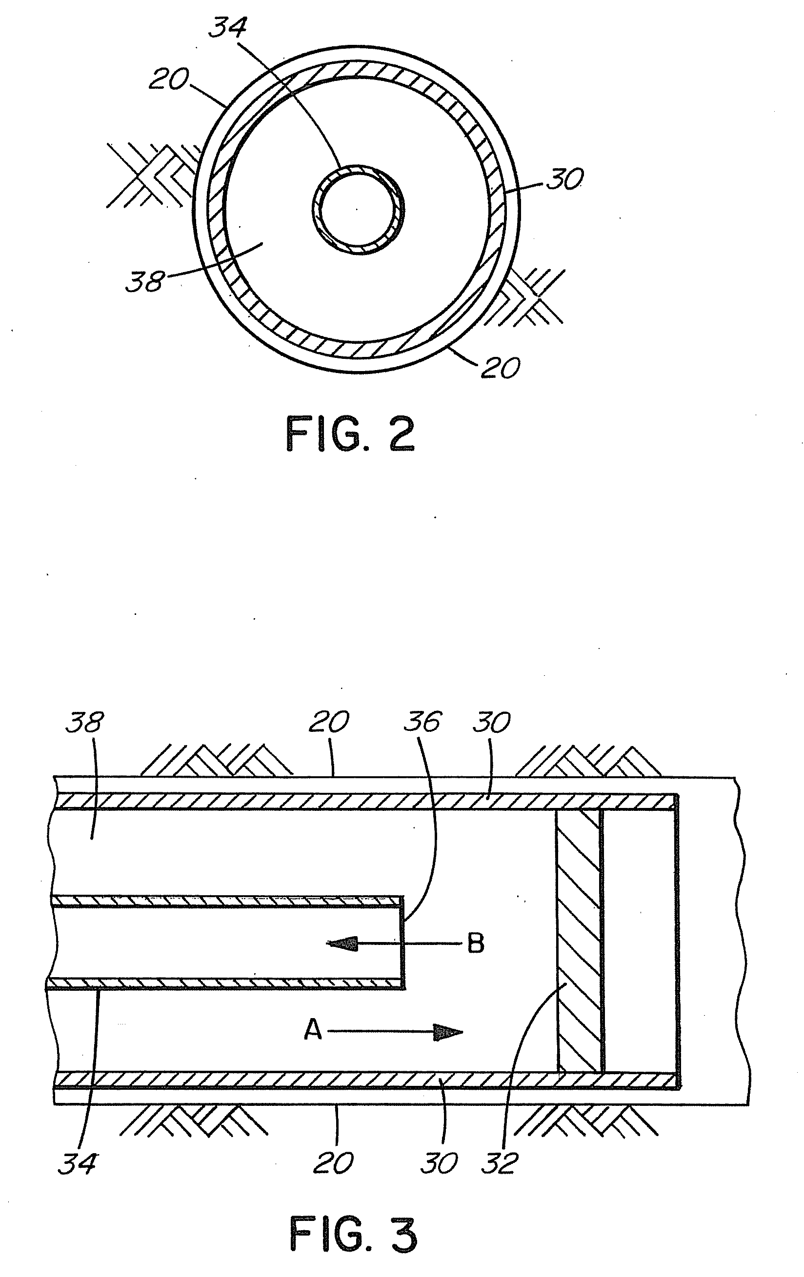
[0007]A wellbore 20 extends from the ground surface 22 to hot rock strata 24 at a depth underground having sufficient heat for use in the system, for example a depth in the range of 15,000 to 28,000 feet. It could require more or less depth depending on the heat desired and the local lithology. The wellbore 20 comprises a first section 26 extending generally vertically to the desired depth or strata and a second section 28 extending generally horizontally within that hot rock strata 24. The wellbore 20 is thus approximately L-shaped. The second section 28 has a length sufficient to allow contact time for heating of the water injected into the piping in the wellbore to a desired temperature, for example a temperature in the order of 150° C. to 200° C.

[0008]The wellbore is lined throughout with a casing 30 comprising steel piping. The bottom end of the casing, at the end of the borehole, is closed with a permanent plug 32. The casing and plug provide a sealed system whereby the interi...


PUM


Abstract

A geothermal system in deep, hot, dry rock has closed loop circulation, in which the water and steam circulating in the system are protected from any direct contact with the base rock. The system has a single L-shaped bore with a casing that lines the wellbore and has a sealed bottom end. A tubing within the casing has an open bottom end. Water or other liquid or gas is injected under pressure into the casing in the space between the casing and the tubing and is heated by the deep hot rock strata, creating heated liquid or gas which flows into the tubing through its open bottom end and is returned to the surface for use for heating, or in a power plant, or other applications. In a reverse configuration, the working fluid is injected into the tubing and is returned via the space between the casing and the tubing.

Description

BACKGROUND OF THE INVENTION[0001]The invention pertains to geothermal systems for the generation of electricity or heat, in particular geothermal systems that extract heat from deep hot dry rock.[0002]Geothermal systems utilize the high temperatures available at substantial depth underground generally to heat water to produce steam. Where the rock strata are hot and dry, i.e. without naturally-occurring hot aquifers, the system that is normally employed, referred to as an enhanced geothermal system, involves drilling two boreholes and fracturing the rock between them at depth. Water pumped down one borehole travels through the hot, fractured rock to produce heated water, and the heated water is removed from the other borehole for use in a power plant or for heating. Because the water and steam are in direct contact with the base rock, they generally become contaminated with undesirable or toxic gases and chemicals, including hydrogen sulfide, mercury and arsenic. Emission-controllin...

Claims


Application Information

Patent Timeline
Patent Type & Authority Applications(United States)
IPC IPC(8): F03G7/00E21B43/25
CPCF03G7/04Y02E10/16F24J3/086F24T10/30Y02E10/10
Inventor ROGERS, WILLIAM H.SMITH, MICHAEL J.
Owner 7238703 CANADA
Why Eureka
Try Eureka