Method for testing the operability of a tank shutoff valve of a fuel tank system

Inactive Publication Date: 2011-03-24
ROBERT BOSCH GMBH
View PDF5 Cites 18 Cited by
  • Summary
  • Abstract
  • Description
  • Claims
  • Application Information

AI Technical Summary

Benefits of technology

[0025]The very advantageous embodiments of the method according to the present invention illustrated below also make it possible

Problems solved by technology

This tank shutoff valve is normally always closed, so that significant partial va

Method used


Image

  • Method for testing the operability of a tank shutoff valve of a fuel tank system
  • Method for testing the operability of a tank shutoff valve of a fuel tank system
  • Method for testing the operability of a tank shutoff valve of a fuel tank system

Examples


Embodiment Construction

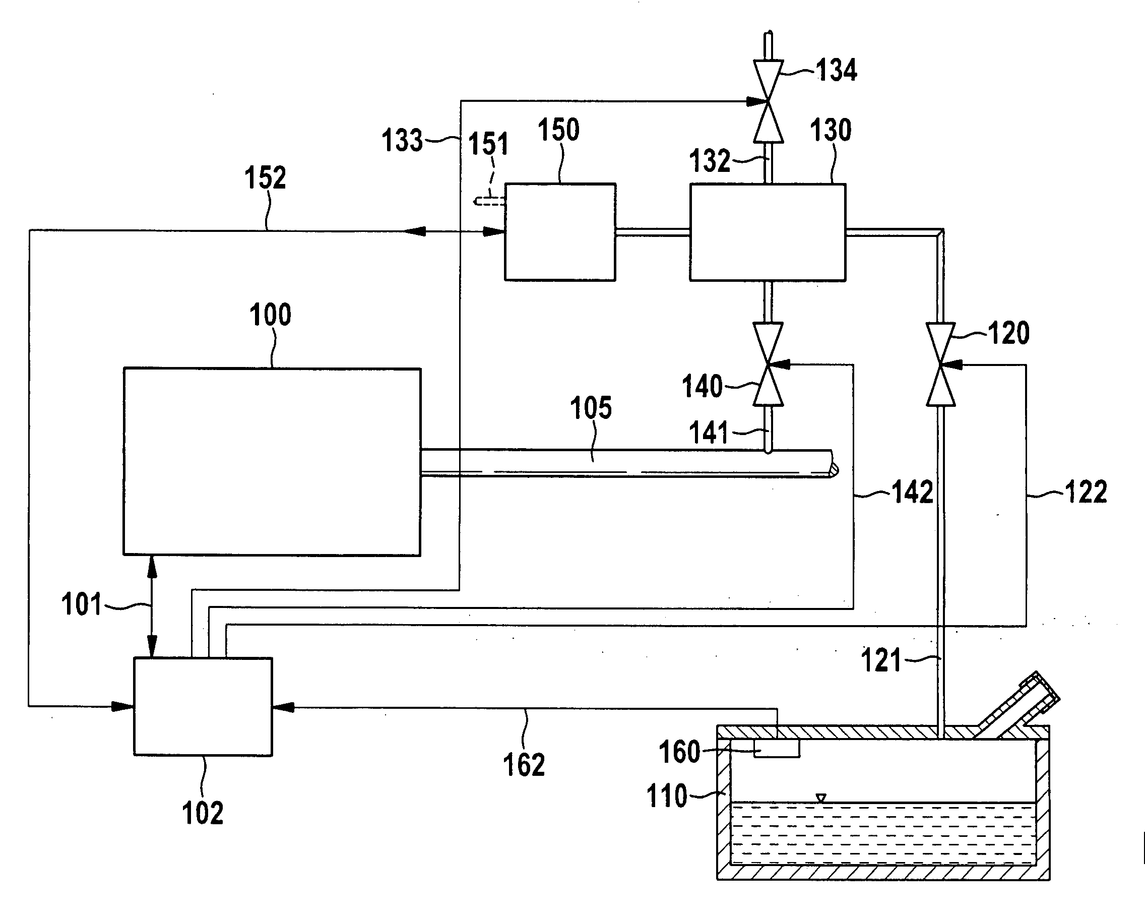
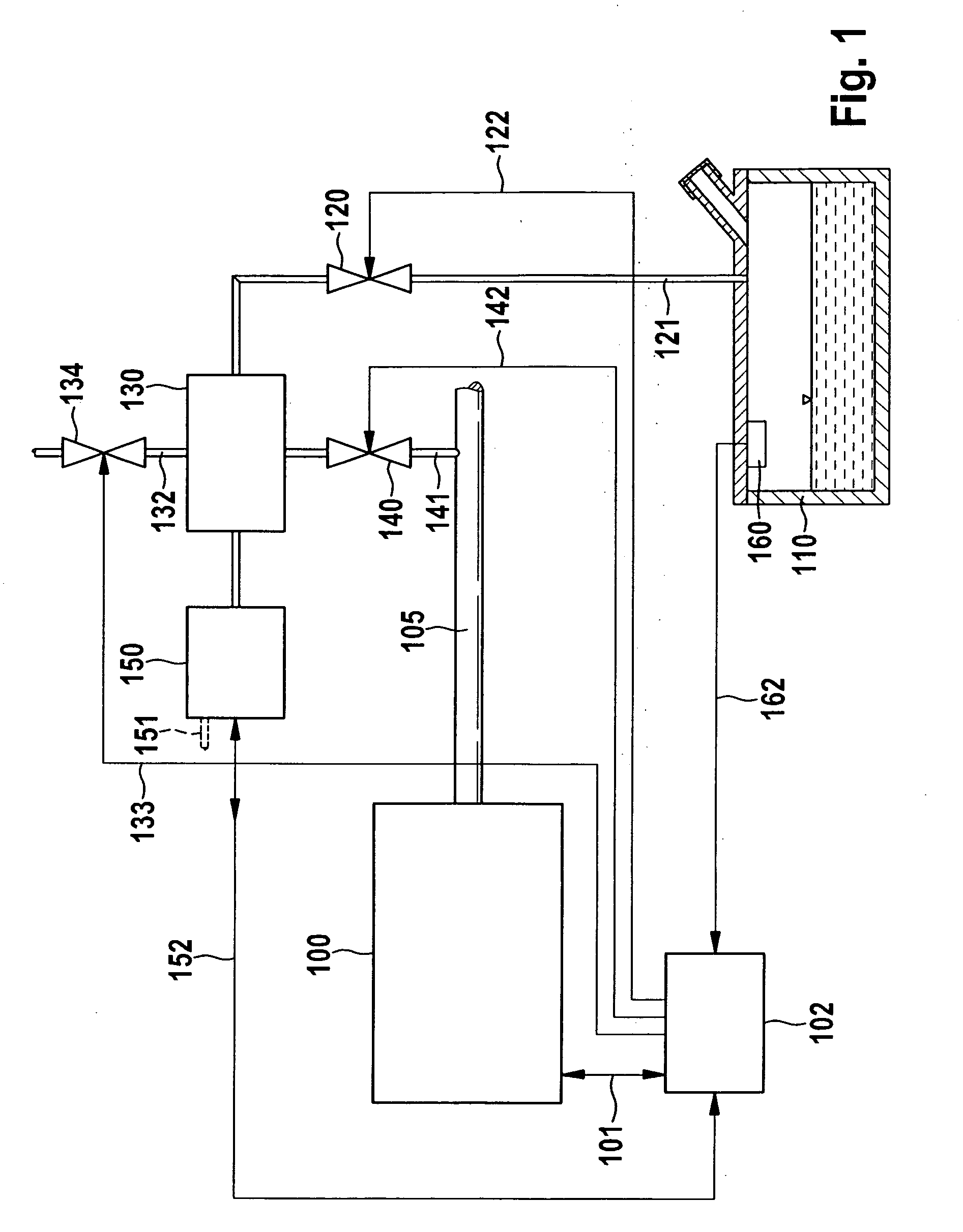
[0045]As shown in FIG. 1, fuel tank system of a vehicle having an internal combustion engine 100 has a tank 110, in which a pressure sensor 160 for detecting the pressure in tank 110 is situated. The output signal of pressure sensor 160 is fed via an electrical line 162 to a control device, such as control unit 102 of internal combustion engine 100. Internal combustion engine 100 is triggered by control unit 102, which is symbolized by a double arrow 101. Triggered means determination and setting of the injection quantity, determination and setting of the injection time, ignition time, and the like. Tank 110 is connected via a line 121 to an activated carbon filter 130. Activated carbon filter 130 is used to adsorb harmful gases outgassed from fuel in the tank. Activated carbon filter 130 has a fresh air line 132. Fresh air line 132 is closable by a shutoff valve 134, which is activatable by control unit 102 via a control line 133. Activated carbon filter 130 is flushed from time to...


PUM


Abstract

A method for testing the operability of a tank shutoff valve of a fuel tank system which is controlled by valves includes performing defined triggering of the tank shutoff valve and simultaneous introduction of an overpressure or partial vacuum into the fuel tank system via a pressure source, and the operability of the tank shutoff valve is determined on the basis of a variable which characterizes the introduction of the overpressure or partial vacuum.

Description

BACKGROUND OF THE INVENTION[0001]1. Field of the Invention[0002]The present invention relates to a method for testing the operability of a tank shutoff valve of a fuel tank system which is controlled by valves.[0003]2. Description of Related Art[0004]Methods and monitoring and control systems for testing fuel tank systems are known from the related art.[0005]Thus, for example, published German patent document DE 196 36 431 A1 discloses a method and a device for testing the operability of a tank ventilation system, in which an overpressure or partial vacuum is introduced into a tank ventilation system and the tightness of the tank ventilation system is determined from the pressure curve. The pressure curve is determined by detecting operating parameters of the pressure source upon introduction of the pressure. A method for testing the operability of a tank ventilation system of a vehicle using a tank tightness test is also disclosed in published German patent document DE 198 09 384 C...

Claims


Application Information

Patent Timeline
IPC IPC(8): G01M3/08
CPCB60K15/03504B60K15/03519F02M25/089F02M25/0809F02M25/0818B60K2015/0319
Inventor HAAG, SILKEPAPE, ANDREASKLUTH, CARSTENNUSSER, UWE
Owner ROBERT BOSCH GMBH
Why Eureka
Try Eureka