Reference vibrator

a vibrator and reference technology, applied in the direction of measurement devices, instruments, structural/machine measurement, etc., can solve the problems of poor the use of the unbalance measurement amount for the measurement of the unbalance amount, and the repeatability of the unbalance measurement device. to achieve the effect of accurate simulation of the vibration force, correct checking of the repeatability of the unbalance measurement device, and more closely checking the repeatability of the unbalance measuremen

Active Publication Date: 2011-03-24
IHI CORP
View PDF51 Cites 4 Cited by
  • Summary
  • Abstract
  • Description
  • Claims
  • Application Information

AI Technical Summary

Benefits of technology

[0011]The present invention was made in view of the above problem, and has an object of providing a reference vibrator that makes it possible to properly check the repeatability of the unbalance measurement device.
[0015]According to the above configuration of the present invention, vibration is caused by the vibration generator fixed to the vibrator body. This contributes to high repeatability of the vibration force, unlike the conventional reference rotor equivalent to the rotary product that is subject to the measurement. As a result, vibrations for repeatability check can be applied to the unbalance measurement device with the accurate vibration force. Thus, variations in vibration force can be eliminated, and the repeatability of the unbalance measurement device can be properly checked.
[0019]According to the above configuration, a stable sine vibration force can be applied to the mount of the unbalance measurement device, by using the inertial vibrator. In this way, vibrations very similar to vibrations generated by the rotary product can be accurately applied to the unbalance measurement device.
[0023]According to the above configuration, by forming the Lissajous circle of the vibration force by two inertial vibrators, the same vibration force as a rotary vibration force generated by the actual rotary product can be simulated. This allows for a more accurate simulation of the vibration force, so that the repeatability of the unbalance measurement device can be checked more closely.
[0024]As described above, according to the present invention, the repeatability of the unbalance measurement device can be properly checked.

Problems solved by technology

An unbalance measurement device is used for the measurement of the unbalance amount.
Therefore, it is necessary to check and calibrate the repeatability of the unbalance measurement device.
However, repeatability of a vibration force of the reference rotor is poor, due to factors such as changes or variations in vibration state caused by environmental conditions and degradation of the reference rotor.
This makes it impossible to judge whether the repeatability of the vibration force of the reference rotor is poor or the repeatability of the measurement device is poor, and so there is a problem of difficulty in properly checking the repeatability of the unbalance measurement device.

Method used


Image

  • Reference vibrator
  • Reference vibrator
  • Reference vibrator

Examples


first embodiment

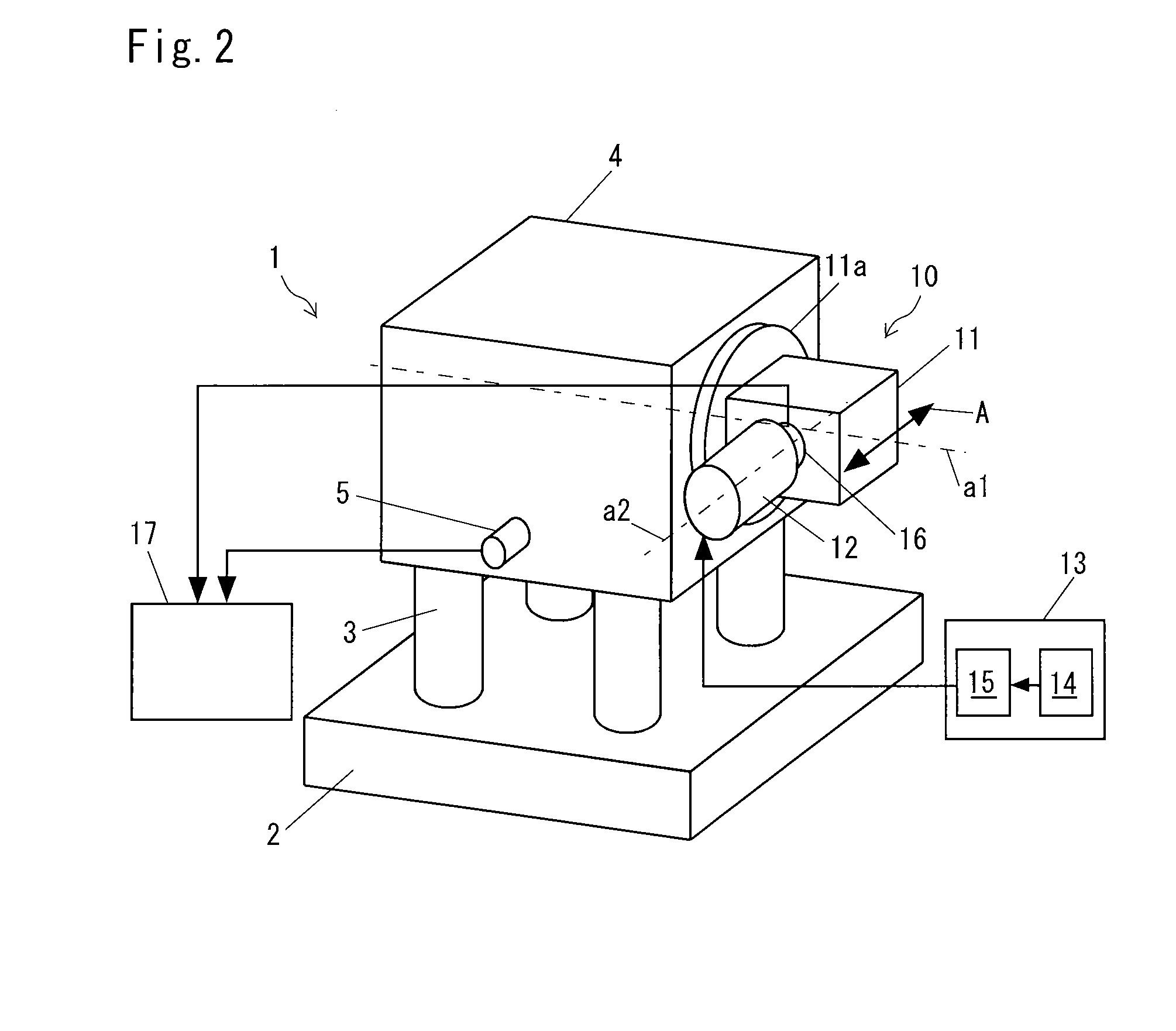
[0029]FIG. 2 is a schematic configuration diagram of a reference vibrator 10 according to the present invention. The reference vibrator 10 in a state of being mounted and fixed to an unbalance measurement device 1 is shown in FIG. 2.

[0030]A configuration of the unbalance measurement device 1 is described first.

[0031]The unbalance measurement device 1 includes: a base 2 fixed on a floor surface or the like; a plurality of rodlike spring members 3 that are secured on the base 2 and function as springs; a mount 4 fixed and supported on the top of the spring members 3; a vibration sensor 5 attached to the mount 4; a rotation detector not illustrated; and a calculator 17 that calculates an unbalance amount and a position.

[0032]The number of spring members 3 and a spring constant of the spring members 3 are set to an appropriate number and value, in accordance with a material (hardness) of the spring members 3 and a frequency (rotation speed) for performing an unbalance measurement.

[0033]...

second embodiment

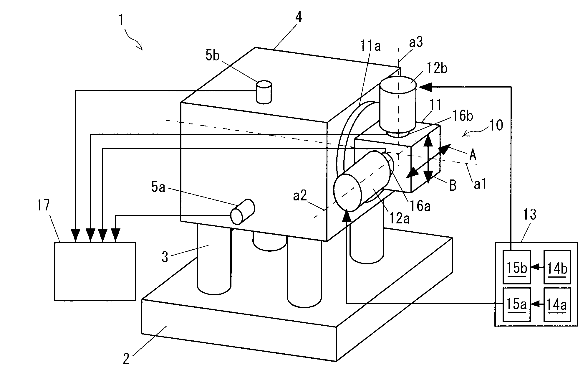
[0058]FIG. 3 is a schematic configuration diagram of the reference vibrator 10 according to the present invention.

[0059]In this embodiment, two inertial vibrators 12a and 12b are fixed to the vibrator body 11 so that vibration directions of the two inertial vibrators 12a and 12b cross each other at right angles. For simplicity, hereafter one inertial vibrator 12a is referred to as a first vibrator 12a and the other inertial vibrator 12b is referred to as a second vibrator 12b. The first vibrator 12a is placed so as to generate a vibration force in a direction of the arrow A (horizontal direction). The second vibrator 12b is placed so as to generate a vibration force in a direction of the arrow B (vertical direction).

[0060]Force sensors 16a and 16b are provided between the first vibrator 12a and the vibrator body 11 and between the second vibrator 12b and the vibrator body 11, respectively. Detection signals of the two force sensors 16a and 16b are input in the calculator 17.

[0061]In...


PUM


Abstract

A reference vibrator 10 of the present invention includes: a vibrator body 11 configured to mount to a mount 4 in an unbalance measurement device 1 to which a rotary product is mounted at the time of unbalance measurement, in a same mounting state as the rotary product; a vibration generator 12 fixed to the vibrator body 11 and that applies vibrations to the vibrator body 11; and a control unit 13 that controls the vibration generator 12. Because vibration is caused by the vibration generator 12 fixed to the vibrator body 11, repeatability of vibration force is high. This makes it possible to apply vibrations for repeatability check to the unbalance measurement device 1 with an accurate vibration force. Thus, variations in vibration force can be eliminated, and the repeatability of the unbalance measurement device 1 can be properly checked.

Description

BACKGROUND OF THE INVENTION[0001]1. Field of the Invention[0002]The present invention relates to a reference vibrator that is mounted to an unbalance measurement device for a rotary product and applies vibrations for repeatability check to the unbalance measurement device.[0003]2. Description of the Related Art[0004]In this application, the term “rotary product” means a device, such as a supercharger, that has a rotor inside.[0005]For example, in manufacture of a high-speed rotary machine such as a supercharger, for inspecting and correcting balance performance of the rotary product at the time of high-speed rotation, a high-speed rotation balance test is conducted to measure an unbalance amount and perform unbalance correction. An unbalance measurement device is used for the measurement of the unbalance amount.[0006]FIG. 1 shows a configuration of an unbalance measurement device 30 disclosed in a Patent Document 1 given below. This unbalance measurement device 30 is configured as a...

Claims


Application Information

Patent Timeline
Patent Type & Authority Applications(United States)
IPC IPC(8): G01M1/02
CPCG01M1/22
Inventor TEZUKA, ATSUSHIOMORI, NAOMICHITSUCHIYA, HIROSHI
Owner IHI CORP
Why Eureka
Try Eureka