
Method of Obtaining DC Microgrid Having Minimized Power Loss

a dc microgrid and power loss technology, applied in the direction of ac network circuit arrangement, printed circuit details, printed circuits, etc., can solve the problems of not meeting all users' requests on actual use, redistribution operations are very dangerous, etc., to achieve the effect of reducing the power loss of a dc microgrid and reducing the power loss

Inactive Publication Date: 2011-03-24
INST NUCLEAR ENERGY RES ROCAEC
View PDF5 Cites 15 Cited by
  • Summary
  • Abstract
  • Description
  • Claims
  • Application Information

AI Technical Summary

Benefits of technology

[0007]The main purpose of the present disclosure is to obtain a DC microgrid having a minimized power loss, where power loss of a DC microgrid is reduced and its service is recovered soon by obtaining a best network configuration.
[0008]To achieve the above purpose, the present disclosure is a method of obtaining a DC microgrid having a minimized power loss, comprising steps of: (a) obtaining power loss of each mesh and state of each switch in a microgrid; (b) obtaining circuit combinations of all meshes to find a best solution with a minimized power loss calculated through[yi+p]=[Sj,Q+m]j=1,…,n;m=ceil(N(0,2));andσ2=β*js*FiFavg;(c) selecting one of the combinations throughWi=∑t=1NWi,tandFavg-FminFmin<ɛuntil a largest output number is obtained, whereWi,t={1rand<FrFr+F0otherwise;(d) adjusting parameters throughn(g+1)={n(g)+1;n(g)=1forFmin(g)=Fmin(g-1)n(g)-1;n(g)=1forFmin(g)=Fmin(g-1)n(g)forFmin(g)<Fmin(g-1);and (e) avoiding taboo rules. Accordingly, a novel method of obtaining a DC microgrid having a minimized power loss is obtained.

Problems solved by technology

Yet, some redistribution operations are very dangerous and the decision may not be based on power loss.
Hence, the prior arts do not fulfill all users' requests on actual use.

Method used


Image

  • Method of Obtaining DC Microgrid Having Minimized Power Loss
  • Method of Obtaining DC Microgrid Having Minimized Power Loss
  • Method of Obtaining DC Microgrid Having Minimized Power Loss

Examples


Embodiment Construction

[0016]The following description of the preferred embodiment is provided to understand the features and the structures of the present disclosure.

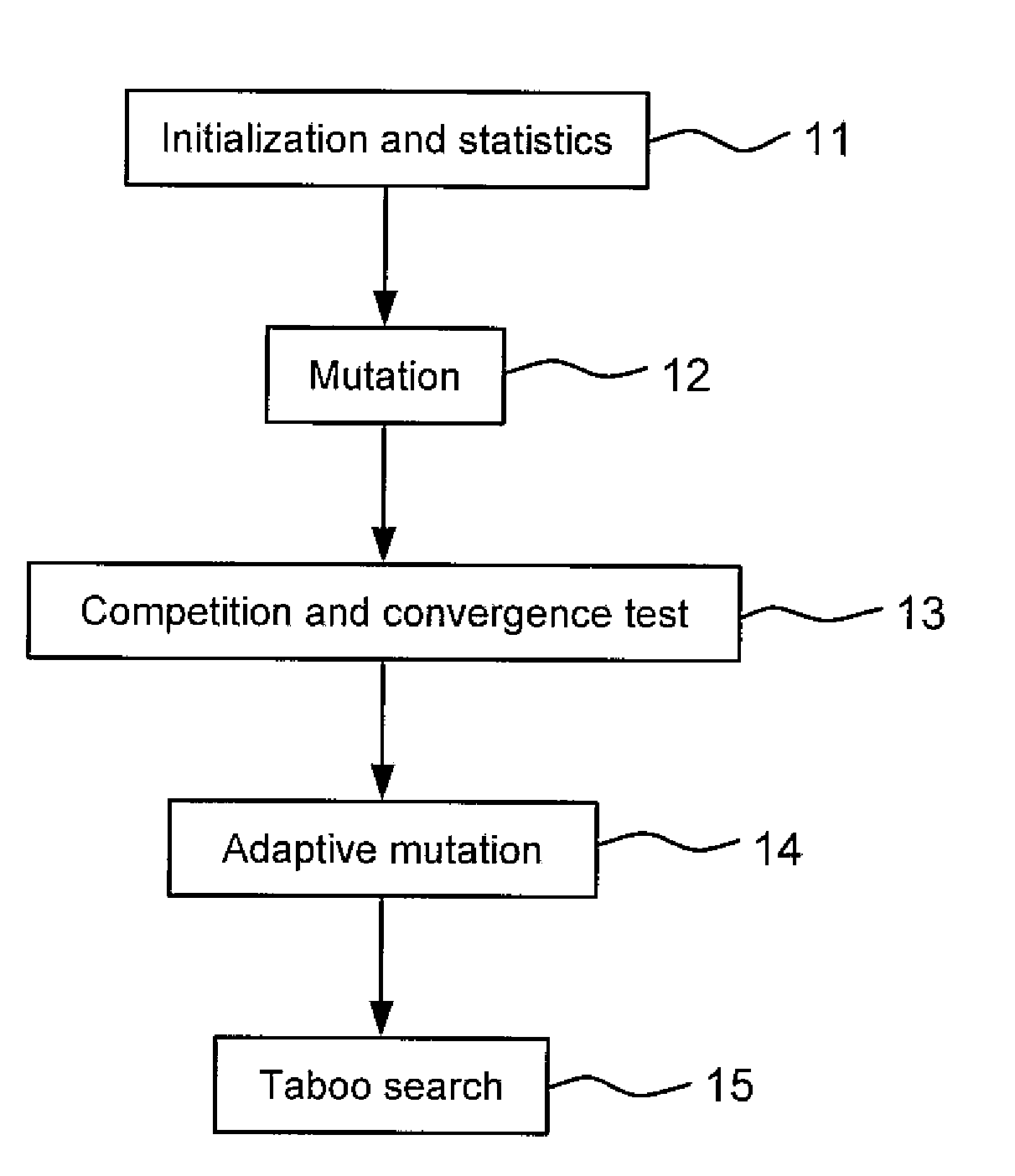
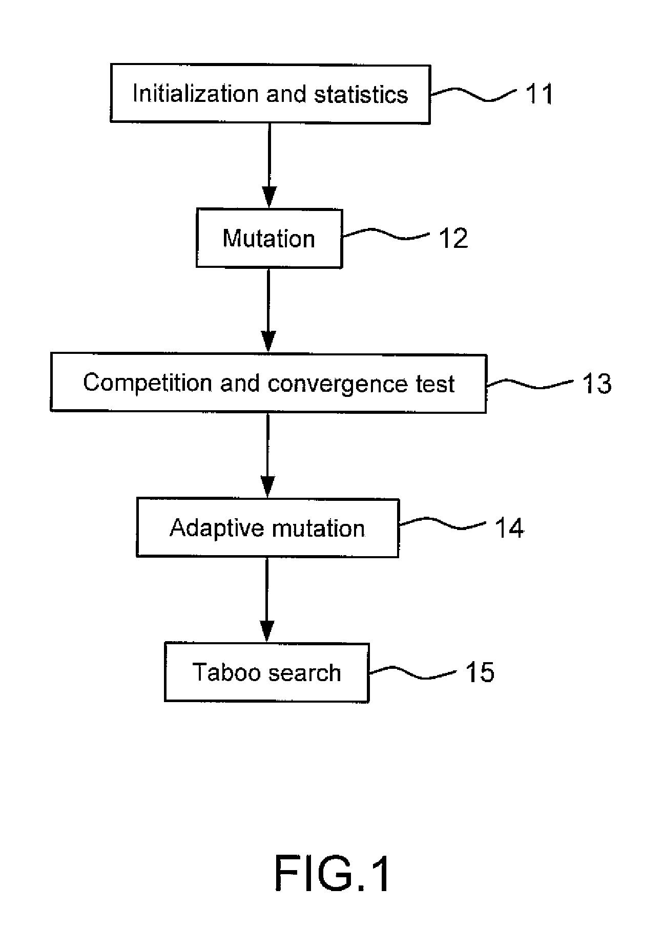
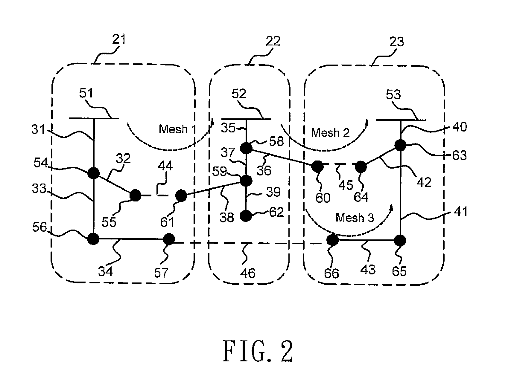
[0017]Please refer to FIG. 1 to FIG. 6, which are a view showing a flow of a preferred embodiment according to the present disclosure; a view showing a DC microgrid; a view showing an arrangement of switches; a view showing combinations of switches; a view showing a robustness test; and a view showing a load test. As shown in the figures, the present disclosure is a method of obtaining a DC microgrid having a minimized power loss. In FIG. 2, the present disclosure is applied to a grid of three renewable energy resources zones (RERZ), comprising a first to a thirteenth sectionalizing switches 31˜43; a first to a third connecting switches 44˜46; and a first to a sixteenth backup switch 51˜66. In the grid, the connecting switches 44˜46 are always open for changing the grid from a radial grid into a mesh grid. In order to change the grid back to...


PUM


Abstract

Power loss of a direct-current microgrid is analyzed. The process includes initialization and statistics; mutation; competition and convergence test; adaptive mutation; and taboo search. Rearrangement of the microgrid can be figured out in a short time. Thus, power loss is minimized and service can be quickly recovered.

Description

CROSS REFERENCE TO RELATED PATENT APPLICATIONS[0001]This application claims priority from Taiwan Patent Application No. 098132229, filed in the Taiwan Patent Office on Sep. 24, 2009, entitled “Method of Obtaining DC Microgrid Having Minimized Power Loss,” and incorporates the Taiwan patent application in its entirety by reference.TECHNICAL FIELD[0002]The present disclosure relates to obtaining a best network configuration; more particularly, relates to obtaining a direct current (DC) microgrid having a minimized power loss, where power loss of a DC microgrid is reduced and its service is recovered soon.DESCRIPTION OF THE RELATED ART[0003]Power resources for general microgrids are renewable energies, like energies generated from photovoltaic devices, wind turbines, fuel cells, hydro plants, etc., where batteries, super capacitors and flywheels are used as energy storage devices. These power resources and energy storage devices usually generate DC voltage or alternative current (AC) v...

Claims


Application Information

Patent Timeline
Patent Type & Authority Applications(United States)
IPC IPC(8): H02J3/00
CPCH02J1/00
Inventor OU, TING-CHIA
Owner INST NUCLEAR ENERGY RES ROCAEC
Learn More