
display

Inactive Publication Date: 2011-03-24
SONY CORP
View PDF5 Cites 135 Cited by
  • Summary
  • Abstract
  • Description
  • Claims
  • Application Information

AI Technical Summary

Benefits of technology

[0007]In accordance with principles of the invention, a display which allows accurate burn in prevention is provided.

Problems solved by technology

However, in the technique in Japanese Unexamined Patent Application Publication No. 2002-351403, the degree of degradation in a pixel in a display region is not estimated based on light emission information of the pixel in the display region, so a picture signal is not accurately corrected.
Therefore, it is difficult to prevent burn-in.
As a result, it is difficult to accurately prevent burn-in.

Method used


Image

  • display
  • display
  • display

Examples


Embodiment Construction

, FIGS. 21A and 21B are a front view and a side view in a state in which Application Example 5 is opened, respectively, and FIGS. 21C, 21D, 21E, 21F and 21G are a front view, a left side view, a right side view, a top view and a bottom view in a state in which Application Example 5 is closed, respectively.

DETAILED DESCRIPTION OF THE PREFERRED EMBODIMENTS

[0053]While various embodiments of the present invention have been described, it will be apparent to those of skill in the art that many more embodiments and implementations are possible that are within the scope of this invention. Accordingly, the present invention is not to be restricted except in light of the attached claims and their equivalents.

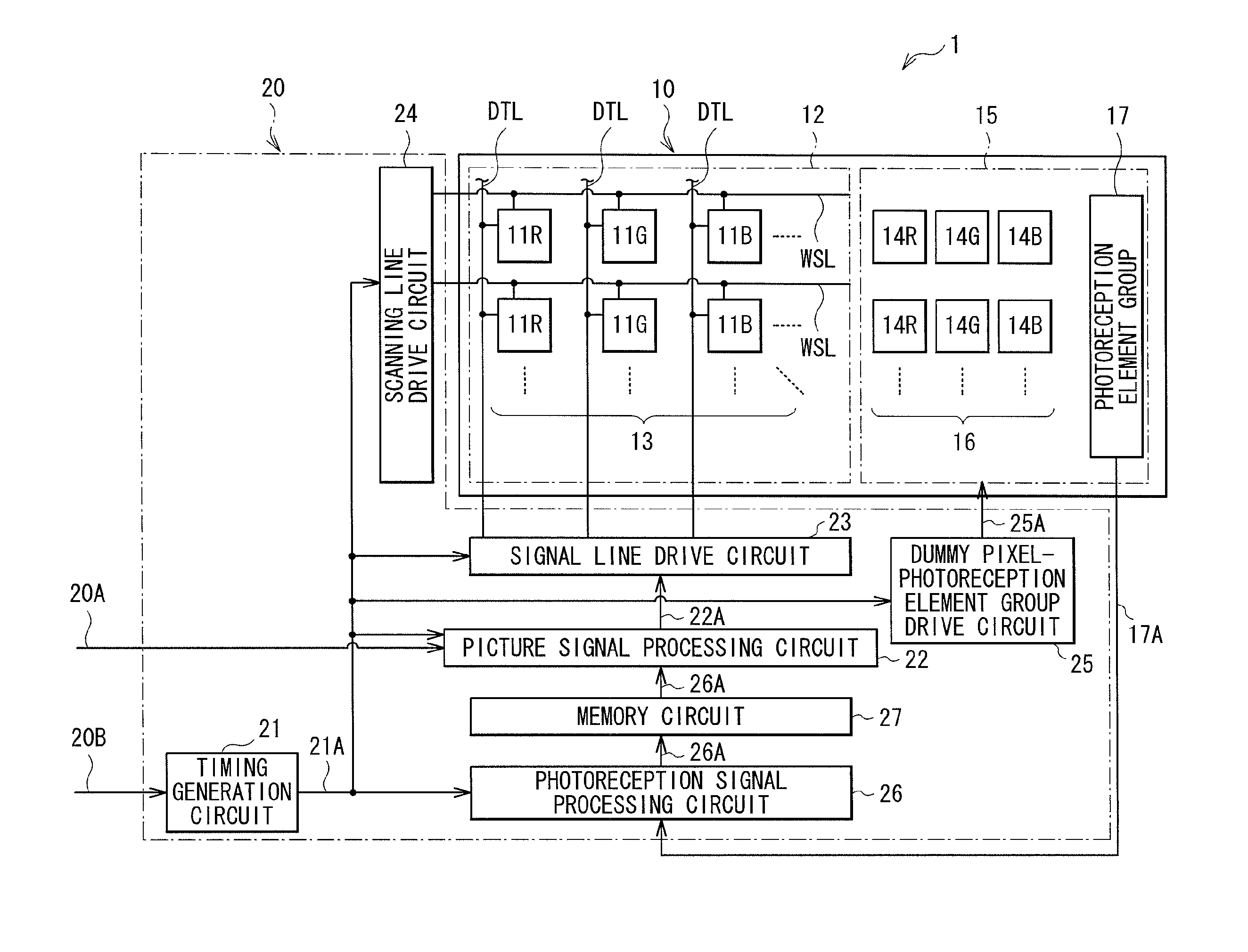
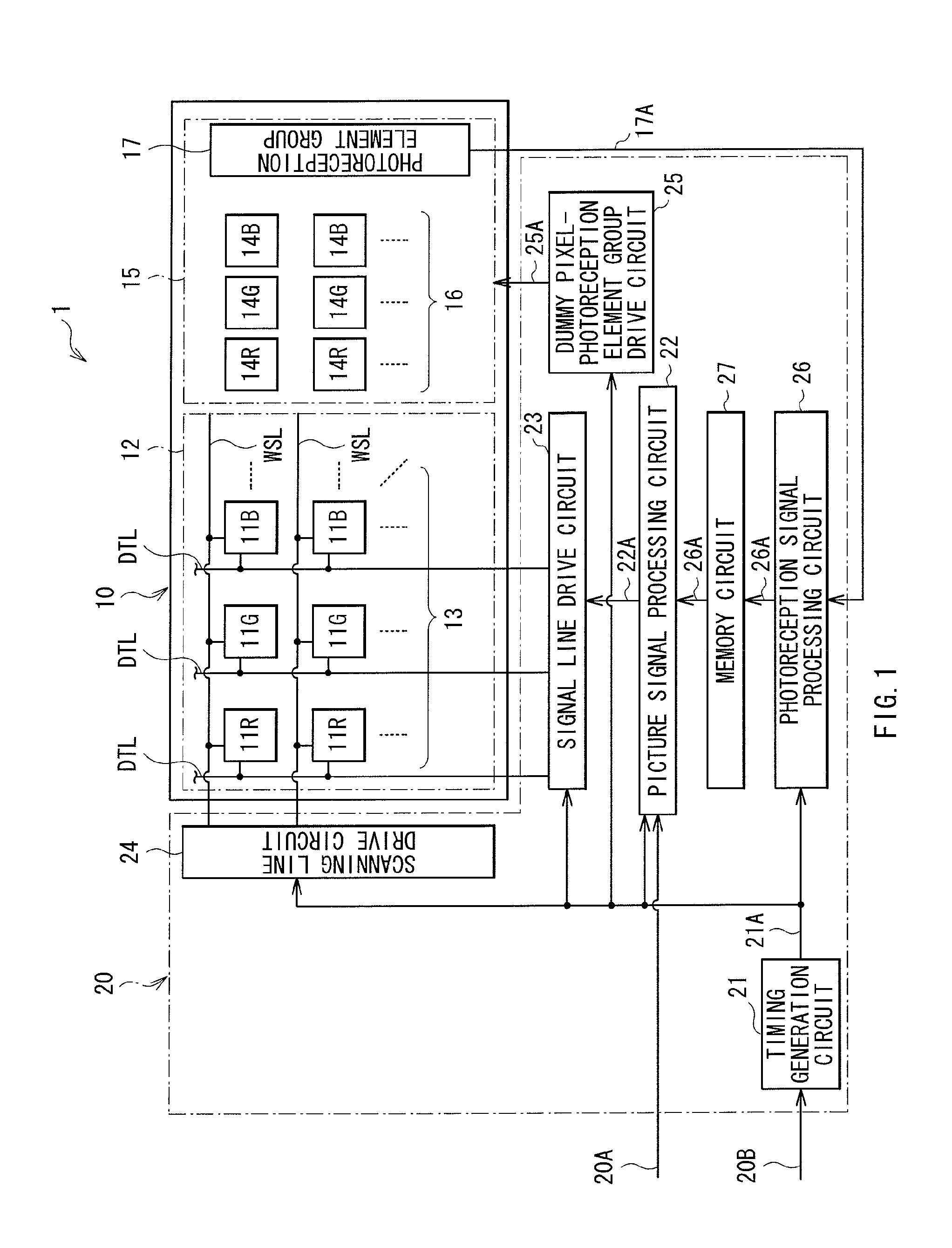
[0054]FIG. 1 illustrates a schematic configuration of a display 1 according to one embodiment consistent with the present invention. The display 1 includes a display panel 10 and a drive circuit 20 driving the display panel 10.

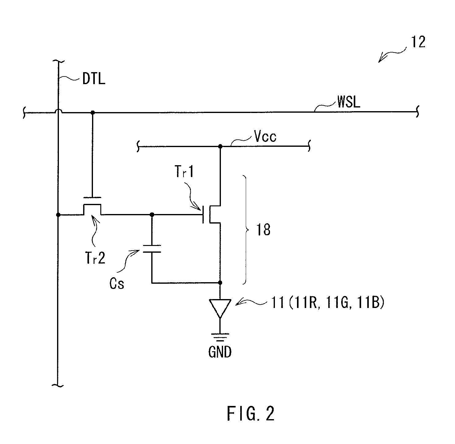
[0055]The display panel 10 includes a display region 12 in whi...


PUM


Abstract

A display unit including a display region including a plurality of luminescence elements, a non-display region including a plurality of luminescence elements and a photoreception element, a drive unit connected to each of the luminescence elements in the display region, a photoreception drive circuit connected to the plurality of luminescence elements in the non-display region, and a photoreception processing unit which receives a signal output from each of the plurality of luminescence elements in the non-display region and outputs a degradation signal to the drive unit, the drive unit providing a signal to the plurality of luminescence elements in the display region based on the degradation signal.

Description

CROSS-REFERENCE TO RELATED APPLICATIONS[0001]The present application claims priority to Japanese Priority Patent Application JP 2009-217182 filed in the Japan Patent Office on Sep. 18, 2009, the entire content of which is hereby incorporated by reference.BACKGROUND OF THE INVENTION[0002]The present invention relates to a display including a light-emitting element in a display panel.Background of the Invention[0003]In recent years, in the field of displays displaying an image, displays using current drive type optical elements of which light emission luminance changes depending on the value of a current flowing therethrough, for example, organic EL (Electro Luminescence) elements as light-emitting elements of pixels have been developed for commercialization. Unlike liquid crystal elements or the like, the organic EL elements are self-luminous elements. Therefore, in a display (an organic EL display) using the organic EL elements, a light source (a backlight) is not necessary, so comp...

Claims


Application Information

Patent Timeline
IPC IPC(8): G09G5/10
CPCG09G3/3233G09G2360/145G09G2320/048G09G2320/029
Inventor NAKAMURA, KAZUOUCHINO, KATSUHIDEHASEGAWA, HIROSHIONO, MUNENORI
Owner SONY CORP
Learn More