Wind turbine

a wind turbine and turbine blade technology, applied in vessel construction, renewable energy generation, greenhouse gas reduction, etc., can solve the problems of turbine start-up, various problems, and drag-type blades are necessarily limited to travelling slower

Inactive Publication Date: 2011-03-24
DESIGN LICENSING INT PTY LTD
View PDF34 Cites 5 Cited by
  • Summary
  • Abstract
  • Description
  • Claims
  • Application Information

AI Technical Summary

Benefits of technology

[0012]In accordance with a first aspect of the present invention there is provided a wind turbine having a central axis; at least a first end plate and a second end plate each mounted transversely to the axis and being arranged to rotate about the axis, the first and second end plates being axially spaced; a plurality of turbine blades extending between the first and second end plates and arranged to rotate about the axis; and at least two substantially diametrically opposed wind barriers, each wind barrier extending substa

Problems solved by technology

Drag-type blades are necessarily limited to travelling slower than the prevailing winds.
Nonetheless, various problems have been experienced in producing efficient VAWT for commercial applications.
One problem is in turbine start-up, and operation in light winds.
Another problem experienced is in spacing turbines.
Further research and development has demonstrated that the presence of such ‘cups’ has a significant impact on the aerodynamic properties of the

Method used


Image

  • Wind turbine
  • Wind turbine
  • Wind turbine

Examples


Embodiment Construction

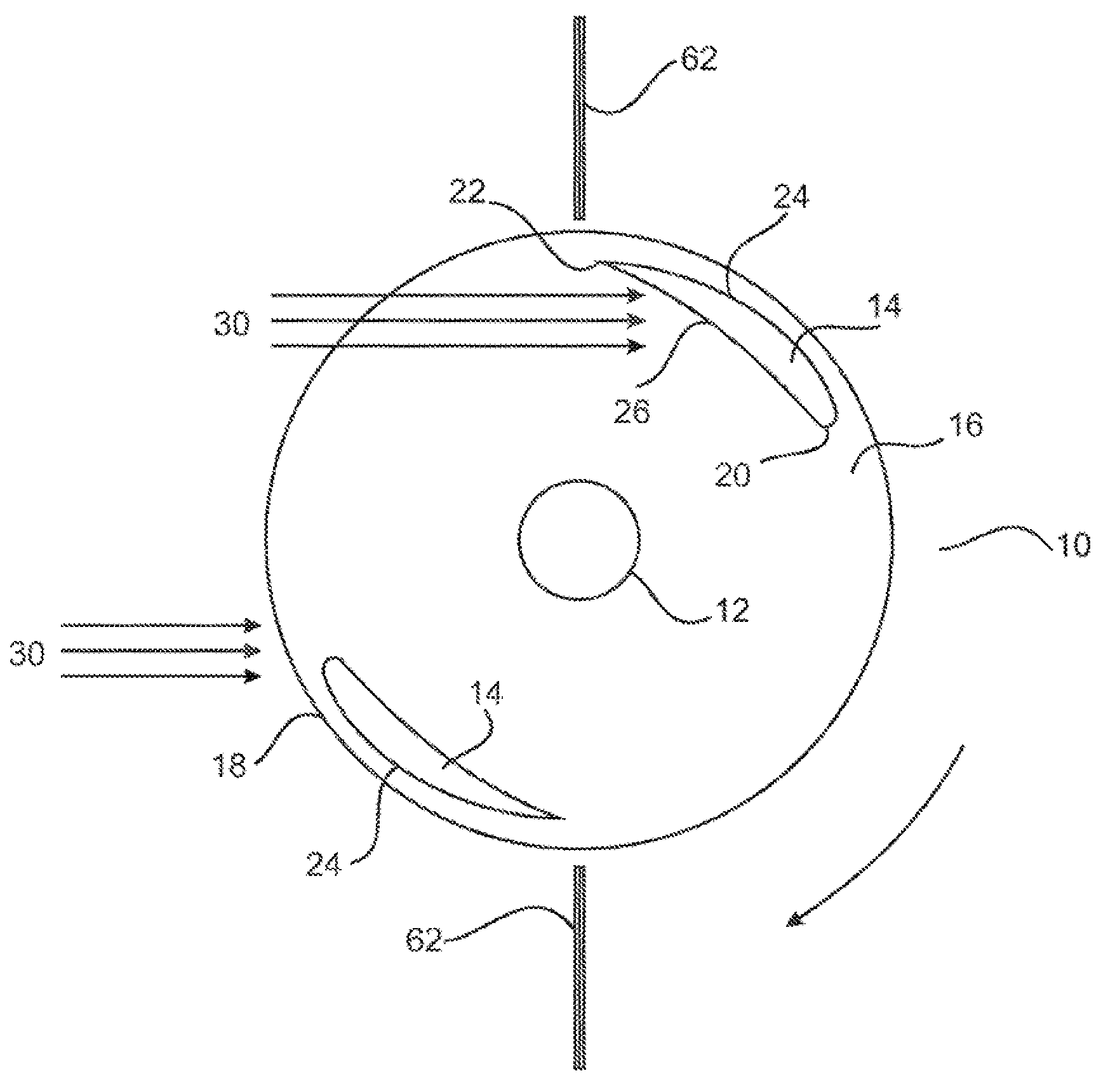
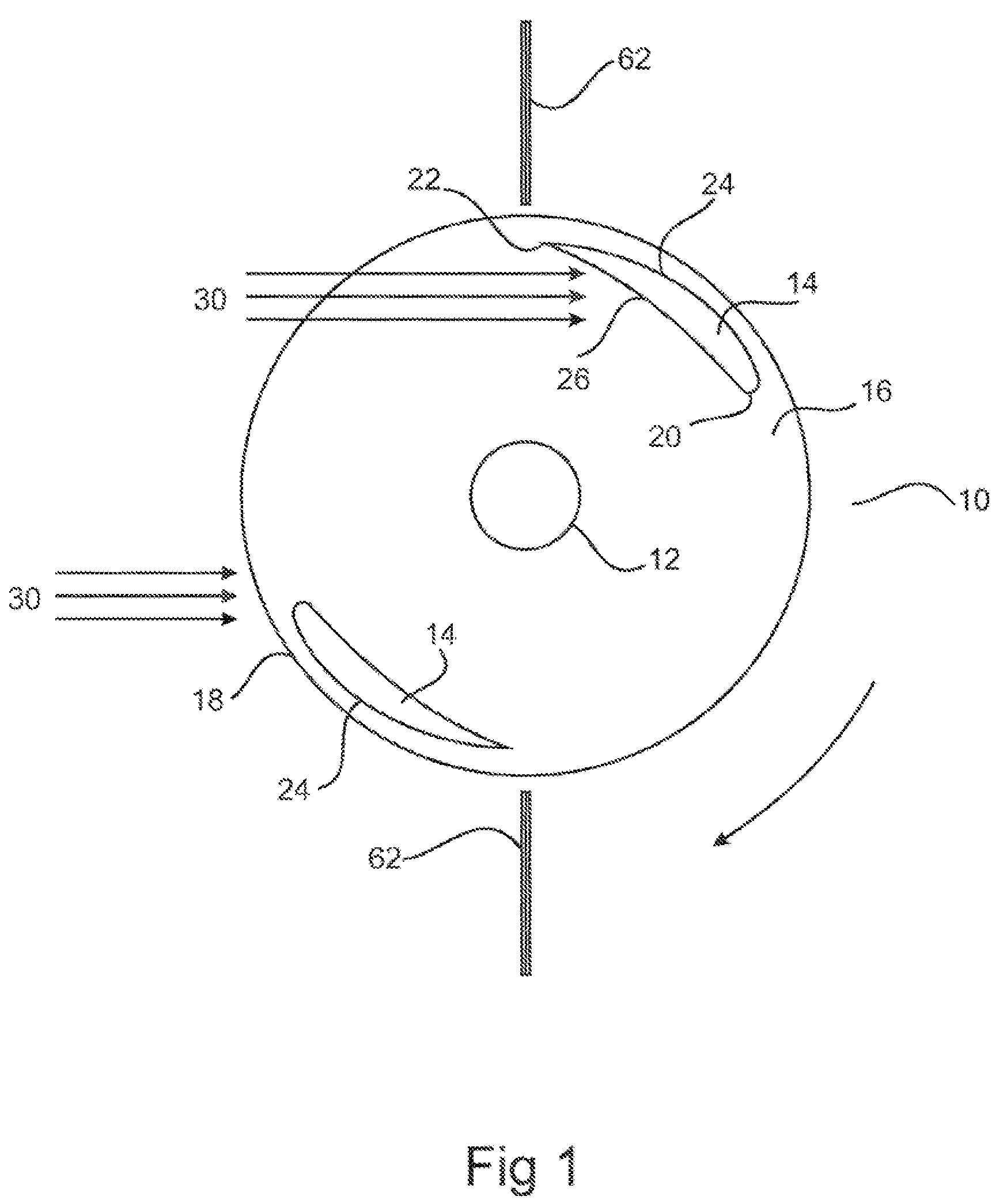
[0031]FIG. 1 shows a cross-section of a wind turbine unit 10. The wind turbine unit 10 of this embodiment has an axle 12 located about a central axis, two blades 14 and two end plates 16.

[0032]The end plates 16 are parallel, circular, and centred around the axle 12. In cross section they define an outer circumference 18 of the wind turbine unit 10. The distance from the central axis to this outer circumference can be considered the turbine radius.

[0033]The turbine unit 10 has a first end plate 16 and a second endplate 16, which are axially spaced and act to define a first axial end and a second axial end of the turbine unit 10. Turbine blades 14 extend between the first and second end plates 16. As the end plates 16 rotate about the axis, the blades 14 thus also rotate about the axis.

[0034]The blades 14 are diametrically opposed about the axle 12. Each blade 14 has a leading edge 20 and a trailing edge 22, connected by an outer surface 24 and an inner surface 26. The blade 14 has an...


PUM


Abstract

A wind turbine arranged to operate in confined area is disclosed. The wind turbine is constrained within two axially displaced end plates and diametrically opposed wind barriers. The wind barriers are parallel to the axis and extend between end plates. The wind barriers each having an axially extending inner edge radially spaced from an outer swept surface of the turbine blades by less than 20% of the turbine radius. In another embodiment, there is disclosed a 2-dimensional array of wind turbines, with wind barriers being arranged between parallel axes.

Description

CROSS-REFERENCE TO RELATED APPLICATIONS[0001]This application is a continuation of International Patent Application No. PCT / AU2009 / 000567 filed May 7, 2009 which claims benefit of priority to Australian Patent Application Nos. 2008902218 filed May 7, 2008 and 2008902592 filed May 26, 2008, the contents of which are incorporated herein by reference in their entirety.FIELD OF THE INVENTION[0002]The present invention relates to wind turbines. More particularly, it relates to wind turbines having an axis of rotation generally perpendicular to wind direction. Such turbines are generally designated as cross-flow turbines. They are also referred to as ‘vertical axis’ turbines, although this terminology can be misleading.BACKGROUND OF THE INVENTION[0003]Wind turbines can be generally divided into two types: ‘horizontal axis’ wind turbines (HAM) haying an axis of rotation arranged to be aligned with prevailing wind direction; and cross-flow or ‘vertical axis’ wind turbines (VAWT) having an a...

Claims


Application Information

Patent Timeline
IPC IPC(8): F03D3/06
CPCF03D3/002F03D3/04Y02E10/74F05B2240/214F03D3/065F03D3/02F03D3/062
Inventor ATTEY, GRAEME SCOTT
Owner DESIGN LICENSING INT PTY LTD
Why Eureka
Try Eureka