
Controller And Control Method For A Motorised Vehicle

Active Publication Date: 2011-03-24
PENNY & GILES CONTROLS
View PDF14 Cites 15 Cited by
  • Summary
  • Abstract
  • Description
  • Claims
  • Application Information

AI Technical Summary

Benefits of technology

[0015]The technique of the technology disclosed can be used instead of, or in addition to, IR compensation techniques. Where the technique of the technology disclosed is used in combination with IR compensation techniques, the use of the technology disclosed allows the error in IR compensation to be significantly compensated for, while maintaining stability and control of the motorised vehicle.
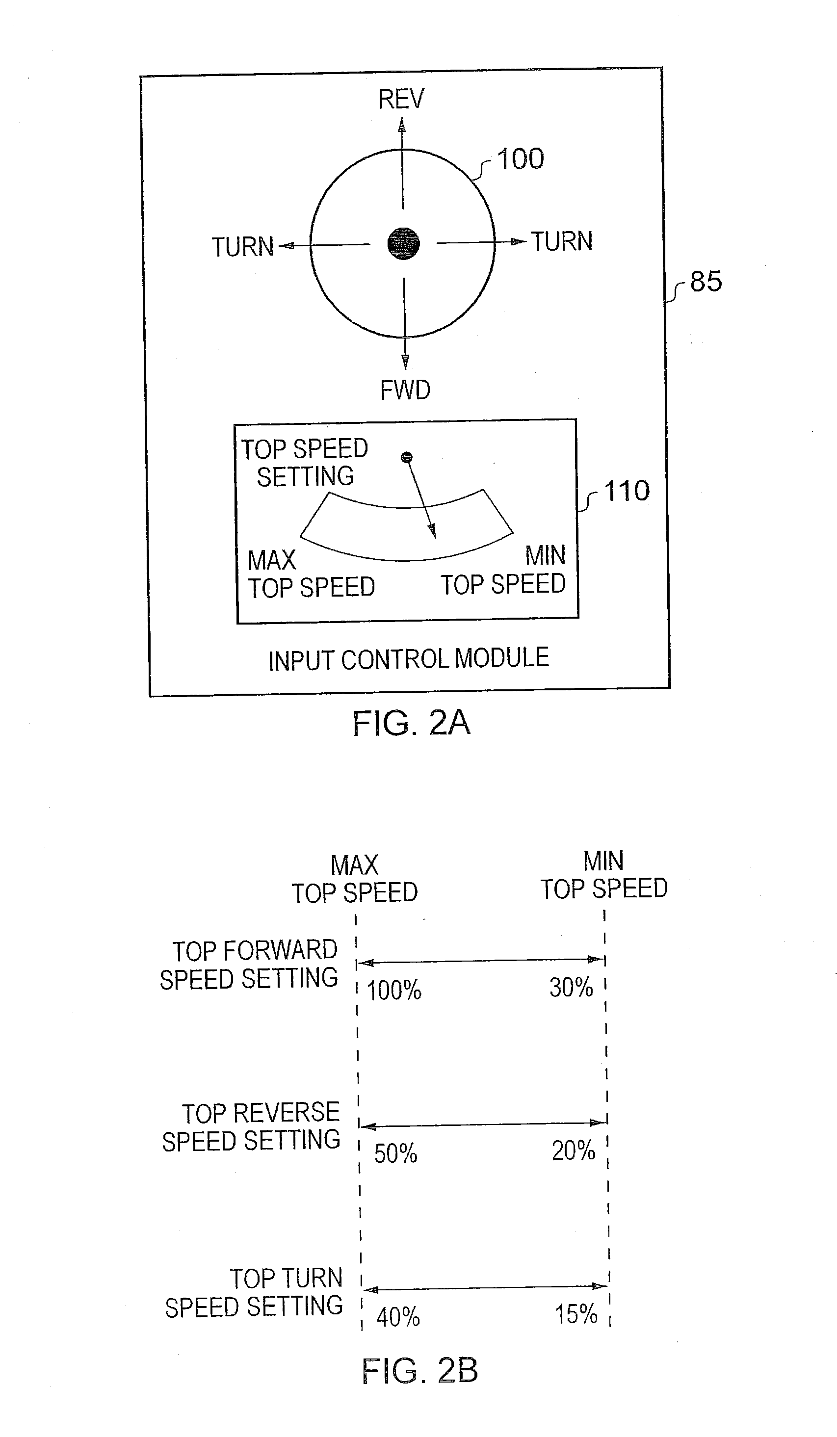
[0016]There are a number of choices as to the input signals which could be boosted in order to boost the top speed in the presence of the loading condition. However, in one embodiment the input signals include a top speed setting selectable via the user input device. In such cases, the control signals generated by the drive control circuitry will be dependent on the top speed setting. In such embodiments, on detection of occurrence of the loading condition, the speed assist circuitry can be arranged to boost the top speed setting selected via the user input device, which will have the effect of boosting top speed in the presence of the loading condition.
[0020]In one embodiment, the manner in which the scalar increases as the current consumed in driving the driven wheels increases can be fixed, but in an alternative embodiment, that function is programmable. In particular, in one embodiment the controller further comprises a storage for storing a programmable value, the rate at which the value of the scalar increases as the current consumed in driving at least one of the at least two driven wheels increases being dependent on said programmable value. This allows the distributor of the motorised vehicle, and even the end user if desired, to change the programmable value as desired, with the aim of achieving a desired control response from the motorised vehicle.

Problems solved by technology

Such a mechanism thus provides positive feedback to the system on a much slower time frame than IR compensation techniques, since such boosting of the input signals will be naturally damped by the drive algorithms used by the drive control circuitry to generate the control signals.

Method used


Image

  • Controller And Control Method For A Motorised Vehicle
  • Controller And Control Method For A Motorised Vehicle
  • Controller And Control Method For A Motorised Vehicle

Examples


Embodiment Construction

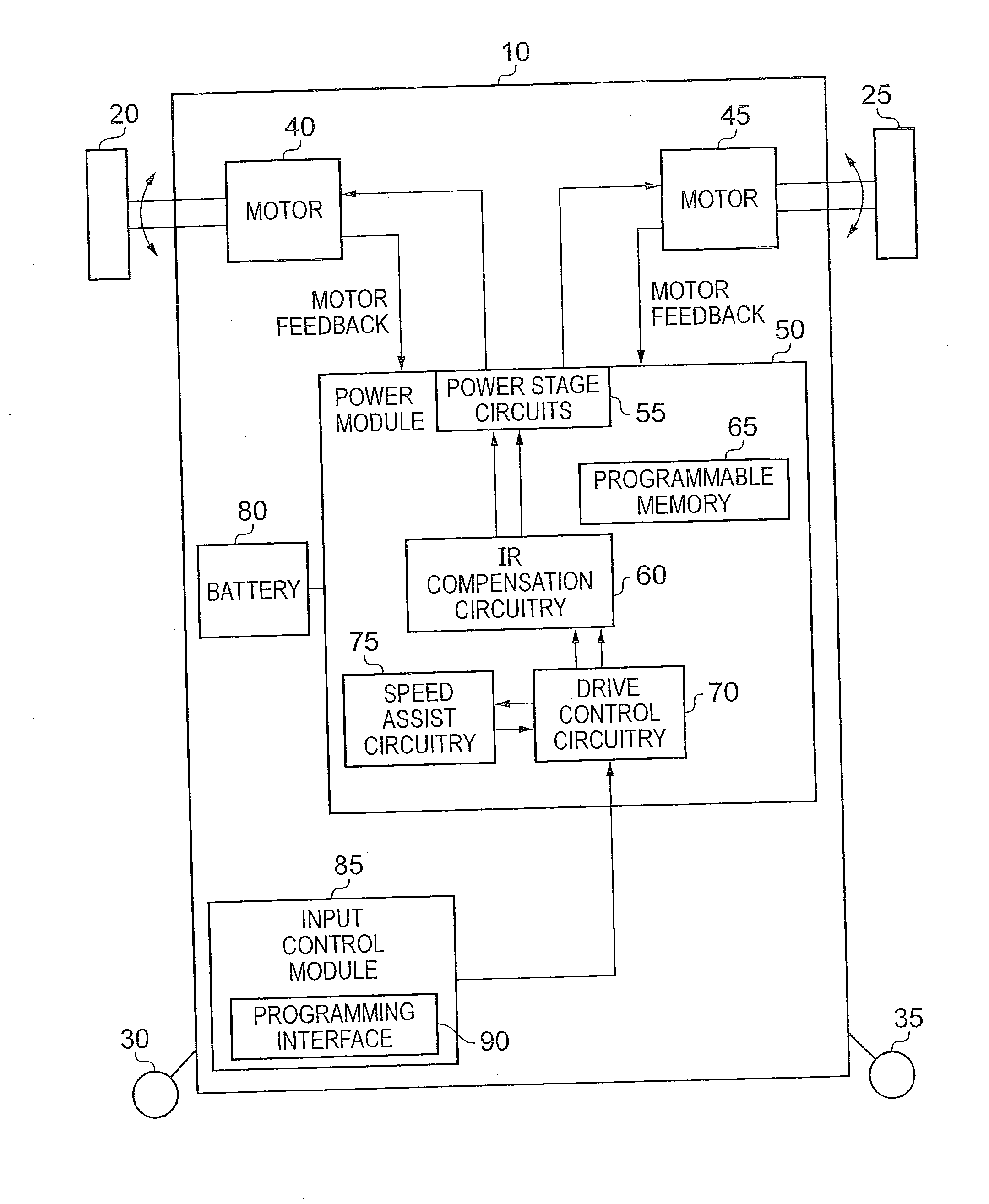
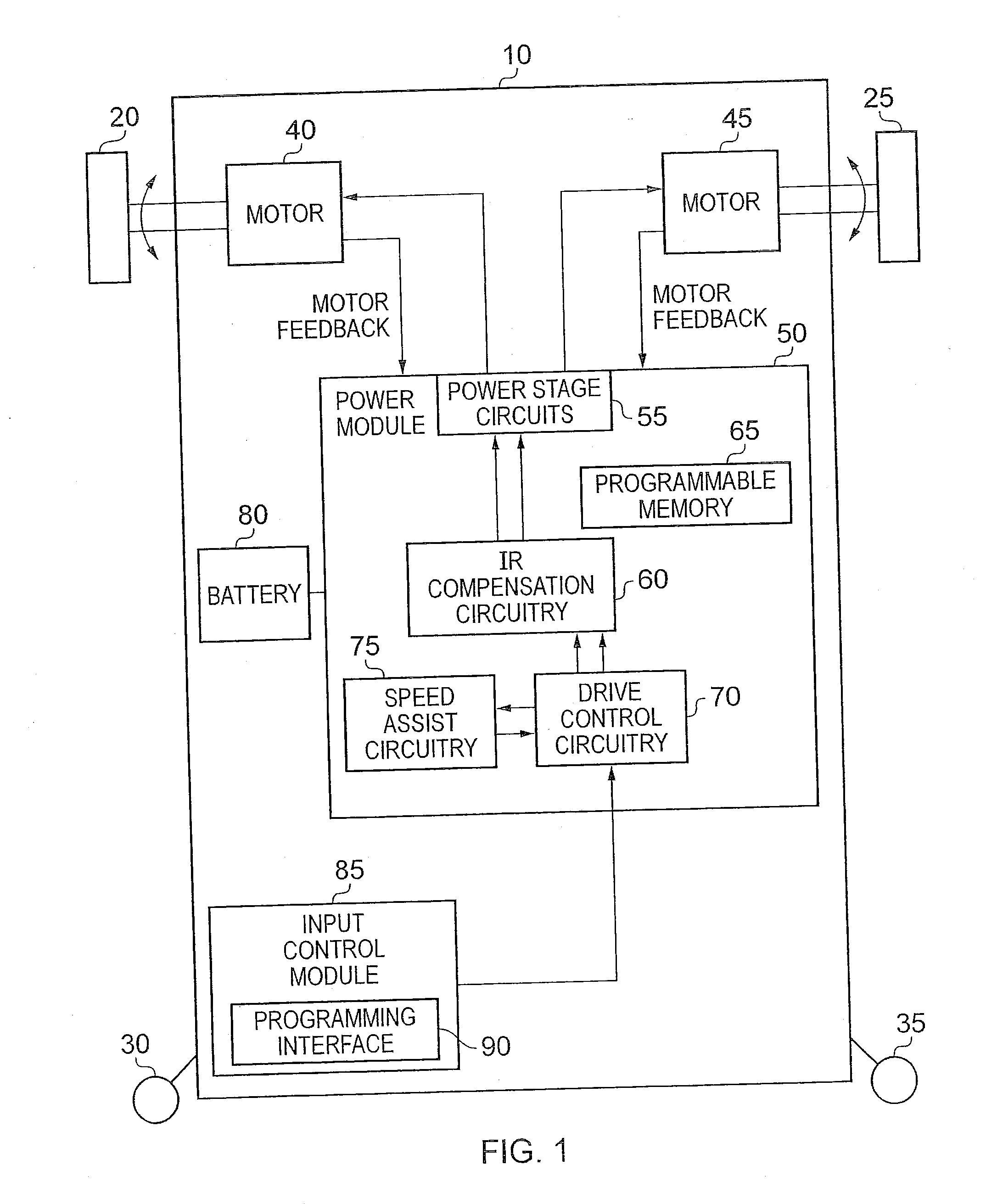
[0047]FIG. 1 is a block diagram of a motorised vehicle in accordance with one embodiment of the technology disclosed. For the purposes of the following discussion, the example where the motorised vehicle is an electric wheelchair will be used. In the example of FIG. 1, the electric wheelchair has a chassis 10 to which two motor driven wheels 20, 25 are connected. Further, a pair of castors 30, 35 are also provided on the front of the wheelchair which rotate to follow the direction of travel of the wheelchair. Each of the two motor driven wheels 20, 25 are driven independently by a motor arrangement. In the embodiment illustrated, each driven wheel 20, 25 is driven by a separate motor 40, 45, respectively. To make the vehicle move forward or backward both wheels are driven in the same direction, whilst to effect a turning of the wheelchair, the two driven wheels 20, 25 are driven in opposing directions.

[0048]Whilst in FIG. 1 the driven wheels are provided to the rear of the wheelchai...


PUM


Abstract

A controller and control method for a motorised vehicle such a wheelchair are provided. The motorised vehicle has at least two driven wheels driven independently by a motor arrangement, and the controller receives a number of input signals from a user input device of the motorised vehicle. The controller comprises drive control circuitry for generating control signals for controlling the driving of the driven wheels by the motor arrangement, the control signals being dependent on the input signals. Speed assist circuitry is responsive to an indication of current consumed in driving the driven wheels to detect occurrence of a loading condition. On detection of occurrence of a loading condition, the speed assist circuitry is then arranged to boost at least one of the input signals in order to boost top speed in the presence of the loading condition. This significantly improves the control of the motorised vehicle in situations where the occurrence of the loading condition may otherwise prevent the vehicle from moving, as for example may occur when seeking to turn the vehicle at low speed.

Description

BACKGROUND OF THE INVENTION[0001]1. Field of the Invention[0002]The technology disclosed relates to a controller and a control method for a motorised vehicle, and in particular to the control of a motorised vehicle having at least two driven wheels driven independently by a motor arrangement. In accordance with such motorised vehicles, turning (or spinning) of the vehicle is typically effected by driving the at least two driven wheels in opposite directions. A typical example of such a motorised vehicle is an electric wheelchair.[0003]2. Background of the Invention[0004]Conventional electric wheelchairs have at least two independently driven wheels. Whilst the motor arrangement used to drive the wheels may comprise a single motor with independent couplings between the motor and the wheels to effect independent drive of those wheels, it is more common that each driven wheel is driven by an independent motor. Often the electric wheelchair will include two or more castors which rotate ...

Claims


Application Information

Patent Timeline
IPC IPC(8): B60L15/20B60L15/10
CPCA61G5/041A61G2203/14B60L15/2009Y02T10/7275B60L15/34B62D11/003B60L15/2036Y02T10/72B60L15/2045B60L15/32
Inventor SHARP, NIGEL PETERGARNETT, GLENN LEIGH
Owner PENNY & GILES CONTROLS
Learn More