Condition monitoring of an underwater facility

a technology for condition monitoring and underwater facilities, applied in the direction of testing/monitoring control systems, process and machine control, instruments, etc., can solve the problems of inability failures and failures still regularly occur in these complex pieces of equipment, and the availability of vessels to perform these operations at short notice may be limited

Active Publication Date: 2011-03-24
BAKER HUGHES ENERGY TECH UK LTD
View PDF5 Cites 54 Cited by
  • Summary
  • Abstract
  • Description
  • Claims
  • Application Information

AI Technical Summary

Benefits of technology

[0017]Accordingly, the invention enables the remote monitoring of the condition of subsea equipment to provided enhanced feedback and abnormal condition detection. The invention

Problems solved by technology

Naturally however, faults and failures still regularly occur within these complex pieces of equipment.
Intervention operations to recover failed modules may be extremely costly and the availability of vessels to perform these operations at short notice may be limited.
Also, failures within the equipment can be potentially harmful to both the environment and personnel safety.
Types of subsea equipment failure include for example:breakdown of resistance in electrical conductors' insulation and/or breakdown of the conductors themselves;leaks within hydraulic and chemical systems;wear within choke valves;wear within valve actuators; andfailure of controlling electronics.
This method has various associated problems

Method used


Image

  • Condition monitoring of an underwater facility
  • Condition monitoring of an underwater facility
  • Condition monitoring of an underwater facility

Examples


Embodiment Construction

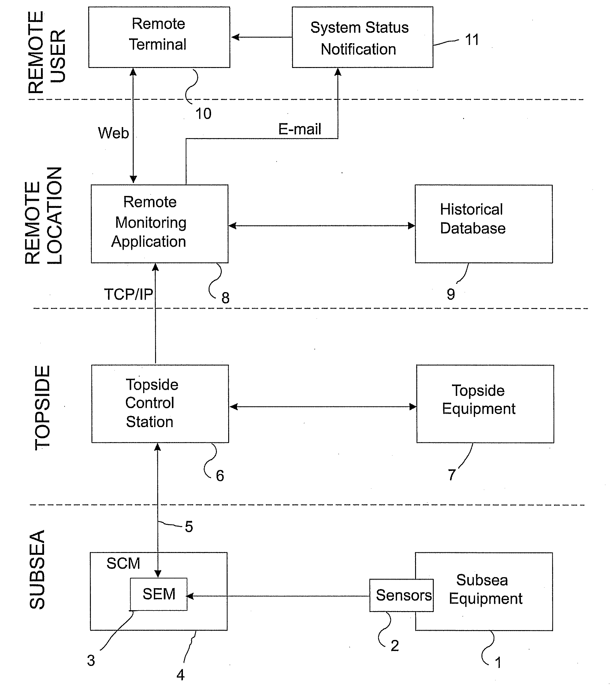
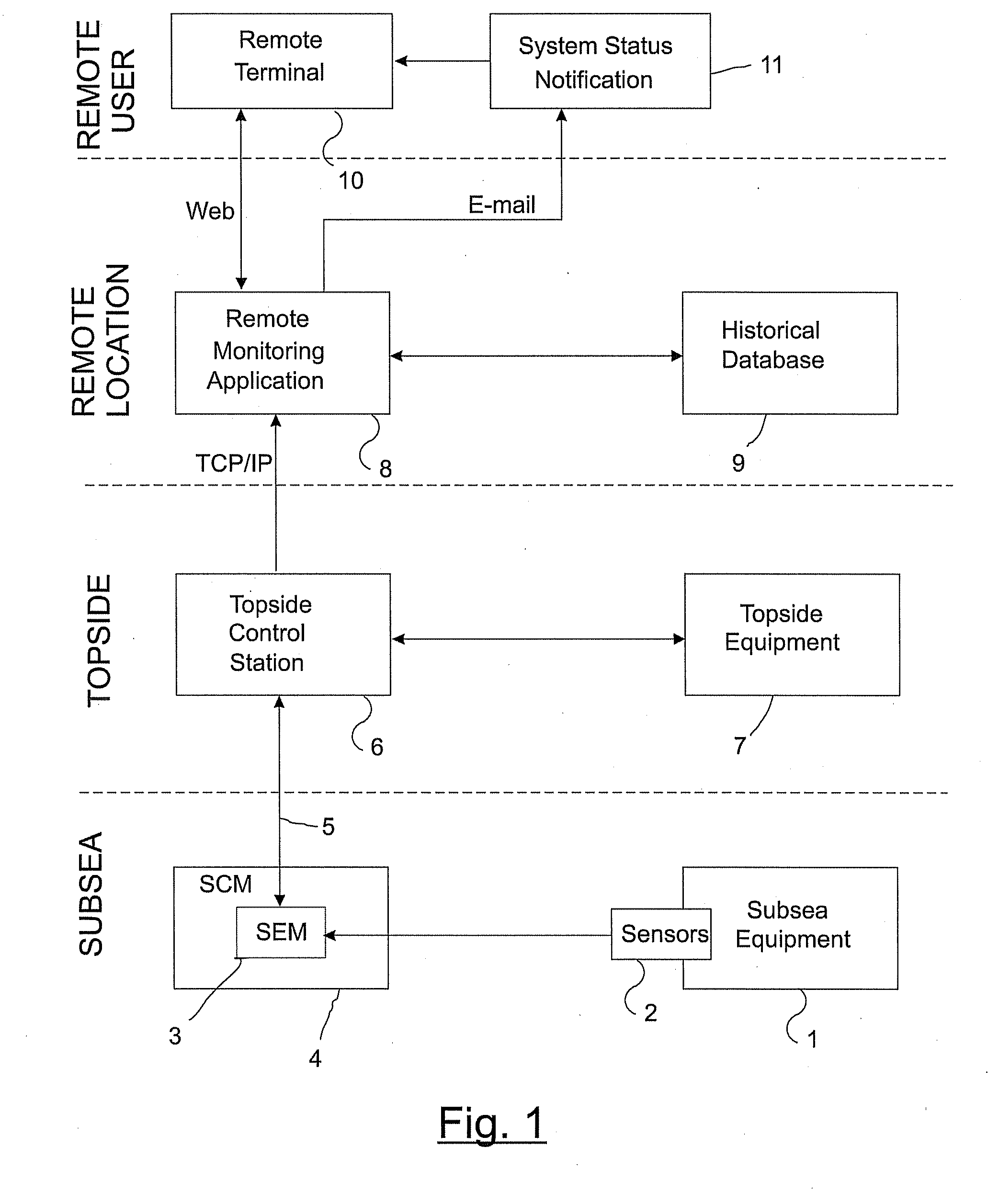
[0036]FIG. 1 schematically shows an overview of an exemplary monitoring system in accordance with the present invention. This system is implemented as an expert system, located remotely from the topside's control system, which interprets data autonomously and provides feedback to an operator on the health of the monitored facility and also provides advice on potential maintenance requirements.

[0037]For simplicity, FIG. 1 divides the system into four locations: subsea, topside, remote location and remote user.

a) Subsea

[0038]A subsea apparatus component 1, for example, but not limited to, a well tree (or “Christmas tree”), manifold, power generation or storage device, communications or power distribution hub, electronics or control module is located at the seabed. This apparatus component 1 has sensors 2 associated with it. Typically a large number of sensors are provided, so that various parameters may be measured. These may include for example pressure, temperature, flowrate of hydr...


PUM


Abstract

A method for monitoring the condition of apparatus located at an underwater facility that includes sensing at least one parameter associated with the apparatus, providing a model of expected behaviour of said at least one parameter, comparing said sensed parameter with said model, and assessing the condition of the apparatus based upon said comparison.

Description

RELATED APPLICATIONS[0001]This application claim priority to United Kingdom Patent Application No. 0916421.1 filed Sep. 21, 2009.FIELD OF THE INVENTION[0002]This invention relates to a method for monitoring the condition of apparatus located at an underwater facility and condition monitoring means for monitoring a component of an underwater facility. In particular, the invention is applicable to an underwater facility such as a subsea hydrocarbon production facility.BACKGROUND OF THE INVENTION[0003]Subsea equipment associated with the production of oil and gas is generally designed with a design life of up to about thirty years. Naturally however, faults and failures still regularly occur within these complex pieces of equipment. Intervention operations to recover failed modules may be extremely costly and the availability of vessels to perform these operations at short notice may be limited. Also, failures within the equipment can be potentially harmful to both the environment and ...

Claims


Application Information

Patent Timeline
IPC IPC(8): G06F15/18G06N5/02
CPCG05B23/0243E21B47/001E21B44/00G05B23/02
Inventor HOLLEY, STUARTELLSON, NICHOLAS
Owner BAKER HUGHES ENERGY TECH UK LTD
Why Eureka
Try Eureka