Headgear Assembly

a headgear and assembly technology, applied in the field of headgear, can solve the problems of not optimizing the comfort of the headgear on the head/neck of the user, not maximizing the stability of the headgear, etc., and achieve the effect of comfortable and stable, better form

Inactive Publication Date: 2011-03-31
RIC INVESTMENTS LLC
View PDF19 Cites 148 Cited by
  • Summary
  • Abstract
  • Description
  • Claims
  • Application Information

AI Technical Summary

Benefits of technology

[0011]Accordingly, it is an object of the present invention to provide a headgear that overcomes the shortcomings of conventional headgear. This object is achieved according to one embodiment of the present invention by providing a headgear assembly for attaching an object to a head of a user. The headgear assembly includes a first beam and a second beam, both of which are adapted to wrap around a back of a user's neck or a back of a user's head. The first beam is generally planer and is adapted to be disposed in a first plane when the headgear assembly is stretched flat. When in this position, the first beam has a first radius of curvature defined in the first plane. The second beam is also generally planer and is adapted to be disposed in the first plane when the headgear assemblies is oriented in a flat position. The second beam has a second radius of curvature defined in the first plane in a same direction as the first radius of curvature. In addition, a first member couples the first beam with the second beam. By providing the first and second beams with a curve in this manner, the headgear assembly assumes a generally spherical shape, at least in the portion that extends over the back of the user's head / neck. This provides a headgear that better forms to the human anatomy, making the device comfortable and stable.

Problems solved by technology

However, they may not optimize the comfort of the headgear on the head / neck of the user.
They may also not maximize the stability of the headgear so that the patient interface device is securely mounted on the user.

Method used


Image

  • Headgear Assembly
  • Headgear Assembly
  • Headgear Assembly

Examples


second embodiment

[0039]Referring now to FIGS. 5-7, a headgear assembly 60 according to the principles of the present invention will be described. As in the previous embodiment, headgear assembly 60 includes first and second beams 62 and 64, respectively, and first and second coupling members 66 and 68. In this embodiment, however, first beam 62 includes end portions 70a and 70b separated by an elastic portion 72. End portions 70a, 70b, second beam 62, and first and second coupling members 66 and 68 are defined as a unitary structure that is semi-rigid, non-stretchy. Examples of materials suitable for forming this unitary structure include: spandex, a lycra lamination, a rubber band that includes a silicone strip, VELSTRETCH, or any combination thereof. As shown in FIG. 7, a pad 74 may be provided over the semi-rigid material to maximize patient comfort. Pad 74 can be provided over a majority of the structure, as shown, or it can be provided only at selected locations.

[0040]The elastic portion of the...

sixth embodiment

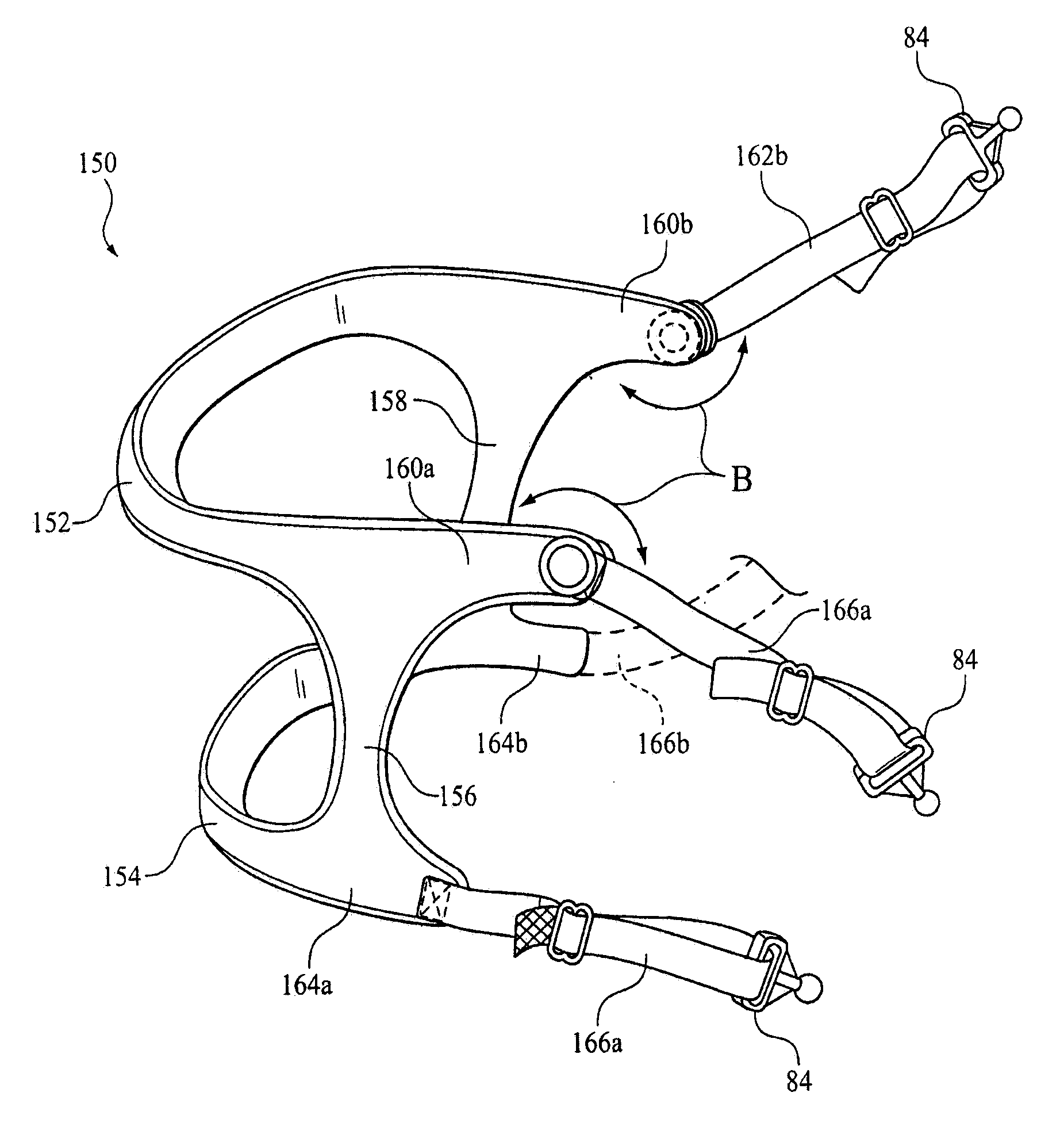
[0045]FIGS. 13 and 14 illustrate a headgear assembly 150 according to the principles of the present invention. As in the previous embodiments, headgear assembly 150 includes first and second beams 152 and 154, respectively, and first and second members 156 and 158 span the first and second beams. Coupling members 162a, 162b are attached to end portions 160a, 160b of first beam 152, and coupling members 166, 166b are attached to end portions 164a, 164b of second beam 154. In this embodiment, coupling members 162a, 162b are rotatably attached to end portions 160a, 160b so that the coupling member can be moved, i.e., rotated, as indicated by arrows B to suit different types of patient interface devices. FIG. 14 also illustrates a first patient interface device 170 that is situated relatively low in the face of the user, and a second patient interface device 180 (shown in dashed lines) that is situation higher on the face. Giving the upper coupling members the ability to rotate allows t...


PUM


Abstract

A headgear assembly for attaching an object to a head of a user is defined by first and second beams adapted wrap around the back of a user's neck and / or head. The first and second beams are generally planer and are adapted to be disposed in a first plane responsive to being stretched flat. The first beam has a first radius of curvature defined in the first plane, and the second has a second radius of curvature defined in the first plane in a same direction as the first radius of curvature. A first member coupling the first beam with the second beam. When donned by the user, the headgear assembly assumes a generally spherical shape that conforms to the back of the human head.

Description

CROSS-REFERENCE TO RELATED APPLICATIONS[0001]This application claims priority under 35 U.S.C. §119(e) from provisional U.S. patent application No. 60 / 842,741, filed Sep. 7, 2006, the contents of which are incorporated herein by reference.BACKGROUND OF THE INVENTION[0002]1. Field of the Invention[0003]The present invention generally relates to a headgear adapted to support an object on the head of a user, and, more particularly, to a headgear having curved beams that enable the headgear to assume a spherical configuration when donned by a user.[0004]2. Description of the Related Art[0005]There are numerous situations where it is necessary to couple an object to the face of a user. For example, non-invasive ventilation and pressure support therapies involve the placement of a patient interface device, which is typically a nasal mask that covers the nose, a nasal / oral mask that covers the nose and mouth, or full face mask that covers the patient face, on the face of a patient. The pati...

Claims


Application Information

Patent Timeline
Patent Type & Authority Applications(United States)
IPC IPC(8): A42B7/00
CPCA61M16/0683
Inventor HO, PETER CHI FAI
Owner RIC INVESTMENTS LLC
Why Eureka
Try Eureka