Clip

a technology of clip and insertion resistance, applied in the field of clips, can solve the problem that the insertion resistance of the clip cannot be substantially increased, and achieve the effect of increasing the working efficiency of the clip insertion operation and not substantially increasing the insertion load (insertion resistance)

Inactive Publication Date: 2011-03-31
DAIWA KASEI IND CO LTD
View PDF22 Cites 2 Cited by
  • Summary
  • Abstract
  • Description
  • Claims
  • Application Information

AI Technical Summary

Benefits of technology

[0010]According to this embodiment, when the anchor portion is pushed into the insertion hole formed in the subject member, the anchor distal end side connecting portion and the anchor proximal end side connecting portion of each of the flexible strips can be substantially uniformly flexed, so that each of the flexible strips can be deformed to be parallel to an axis of the insertion hole. Therefore, in a last stage of an insertion operation of the clip, an angle between the axis of the insertion hole and an outer surface of each of the flexible strips can be maintained in a substantially zero degree. Thus, an insertion load (insertion resistance) of the clip cannot substantially be increased. As a result, working efficiency of the clip insertion operation can be increased.

Problems solved by technology

Thus, an insertion load (insertion resistance) of the clip cannot substantially be increased.

Method used


Image

  • Clip
  • Clip
  • Clip

Examples


Embodiment Construction

[0021]A detailed representative embodiment of the present invention will be described with reference to FIGS. 1 to 6.

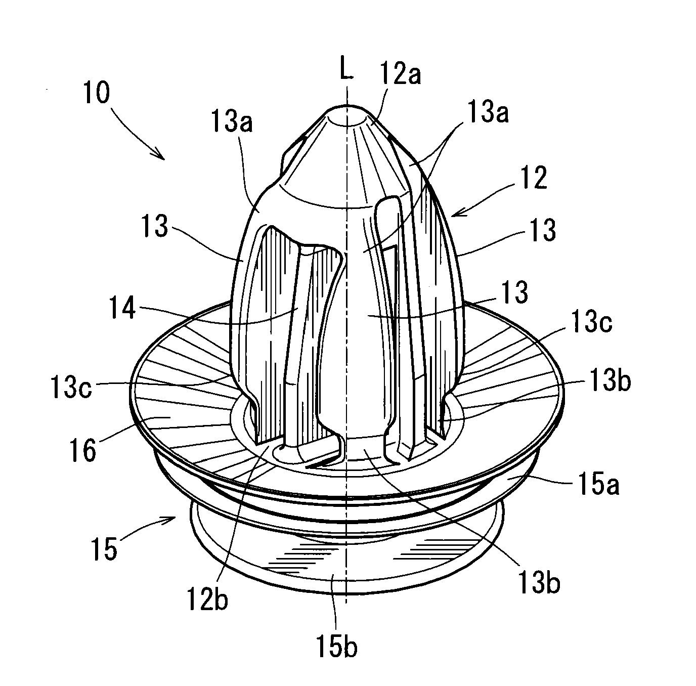
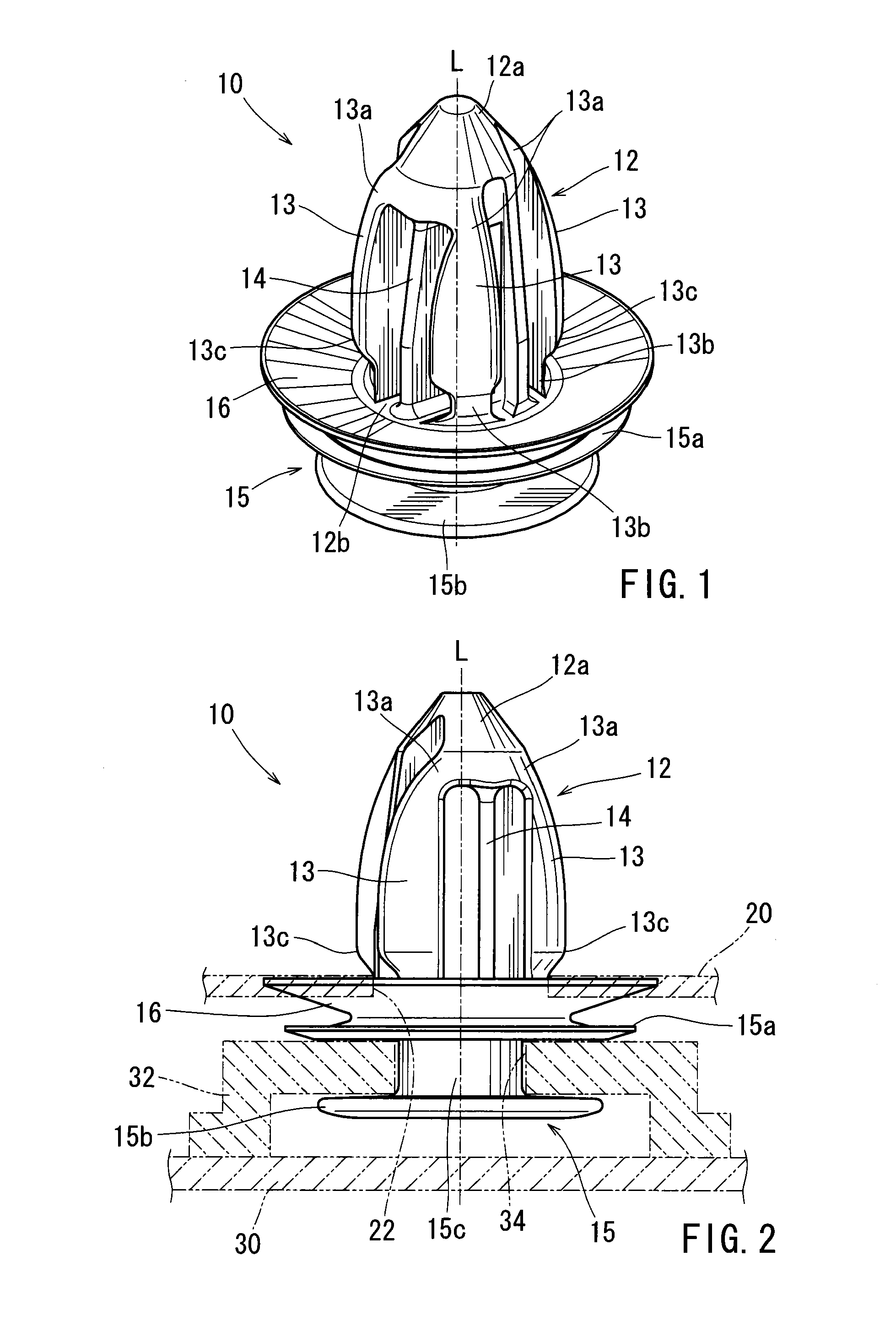
[0022]As shown in FIGS. 1 and 2, a representative clip 10 may preferably be integrally formed as a unit by molding of resin. The clip 10 may preferably include an upper anchor portion 12, a lower connecting portion 15, and a disk portion 16 that is positioned between the anchor portion 12 and the connecting portion 15.

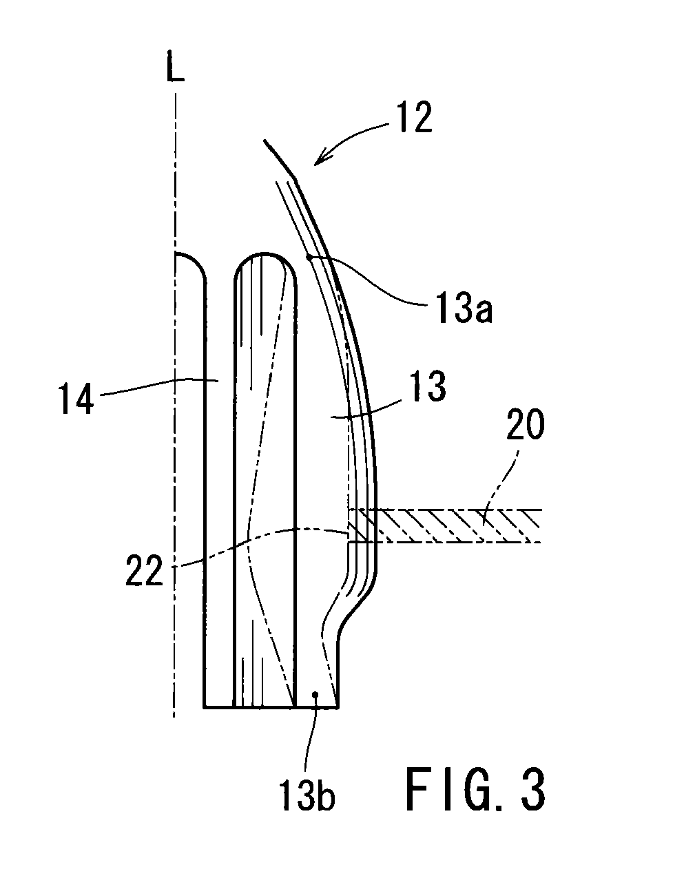
[0023]The anchor portion 12 may preferably include a distal end portion 12a, and a proximal end portion 12b that is connected to the disk portion 16. The distal end portion 12a of the anchor portion 12 is formed into a cone-shaped solid portion (block). Conversely, the proximal end portion 12b of the anchor portion 12 has substantial rigidity so as to function as a base portion of the clip 10.

[0024]The anchor portion 12 may further include a plurality of (four in this embodiment) vertical flexible strips 13 and at least one (two in this embodiment) verti...


PUM


Abstract

A clip may include an anchor portion having a plurality of flexible strips and at least one support strip. Each of the flexible strips is integrally connected to the at least one support strip only via a connecting portion corresponding to a distal end portion of the anchor portion and a connecting portion corresponding to a proximal end portion of the anchor portion. When the anchor portion is pushed into an insertion hole formed in a subject member, the anchor portion is inserted into the insertion hole while each of the flexible strips are flexed toward a longitudinal axis of the anchor portion. Each of the flexible strips is formed such that the difference between a second moment of area of the anchor distal end side connecting portion and a second moment of area of the anchor proximal end side connecting portion is 0-15%.

Description

[0001]This application claims priority to Japanese patent application serial number 2009-226609, the contents of which are incorporated herein by reference.BACKGROUND OF THE INVENTION[0002]1. Field of the Invention[0003]The present invention relates to a clip that is attachable to a subject member (e.g., a vehicle body). More particularly, the present invention relates to a clip that is attachable to the subject member by inserting an anchor portion thereof into an insertion hole formed in the subject member.[0004]2. Description of Related Art[0005]This type of clip is already known and is taught, for example, by Japanese Laid-Open Patent Publication No. 2002-81422. The clip includes an anchor portion (an engagement portion) that is inserted into an insertion hole formed in a subject member. The anchor portion has a plurality of flexible strips. When the anchor portion is pushed into the insertion hole, the anchor portion is inserted into the insertion hole while each of the flexibl...

Claims


Application Information

Patent Timeline
Patent Type & Authority Applications(United States)
IPC IPC(8): F16B2/20
CPCY10T24/44F16B21/086Y10T24/44026Y10T24/309
Inventor IWAHARA, TOSHIOFUJII, KAZUKI
Owner DAIWA KASEI IND CO LTD
Why Eureka
Try Eureka