Twisting translational displacement pump cartridge

a pump cartridge and translational displacement technology, applied in the direction of piston pumps, positive displacement liquid engines, instruments, etc., can solve the problems of high pressure, reduce the propensity for internment, reduce the cost and difficulty involved, and facilitate the insertion force requirements

Active Publication Date: 2011-03-31
VERRILLI BRIAN LEONARD
View PDF6 Cites 23 Cited by
  • Summary
  • Abstract
  • Description
  • Claims
  • Application Information

AI Technical Summary

Benefits of technology

[0030]17.) To provide a pump cartridge design that maintains a thin fluid film around bulkhead walls to aid viscous fluid wetting and reduce propensity for internment of air bubbles at the bulkhead fluid interface.
[0031]The invention is a novel method of designing a pump for delivering a measured quantity of viscous liquid or other liquids through a nozzle for deposit or connection to another passage for extrusion of the fluid. Fluid forced through the exit passage of the pump enters a nozzle that directs it for deposit. A twisting translational displacement pump cartridge comprises:
[0032]A polymer shell with a large cavity between two or more smaller cavities with a series of perpendicular passages through the bulkhead perpendicular to the longitudinal axis, enabling connection of a prime chamber, reservoir, a bulk supply of fluid and a nozzle. Two moveable cores are inserted from each end of the polymer shell; they are slightly smaller than the inside diameter of the smaller cavities. The smaller cavities each contain statically mounted elastomers installed in interior sulcusci adjacent and within close proximity to the bulk feed or prime perpendicular passage, reservoir perpendicular passage and exit perpendicular passage. Perpendicular passages are attached to standard tapers for connection to a nozzle, fluid source, and prime chamber. Installing component parts and joining each side in a fluid tight manner reduces cost and difficulty involved in the manufacture of the polymer shell. A pressure sensor is provided for determining pressure. The gear and bearing surfaces allow rotation of the polymer shell.
[0033]Alternately, the polymer shell can be made in one piece if refill from a bulk supply of fluid is not required. The polymer sh...

Problems solved by technology

Constrictive nozzle designs, a long fluid path combined with high viscosity liquids cause high pressures, when this occurs the pump leaks fluid from aro...

Method used


Image

  • Twisting translational displacement pump cartridge
  • Twisting translational displacement pump cartridge
  • Twisting translational displacement pump cartridge

Examples


Embodiment Construction

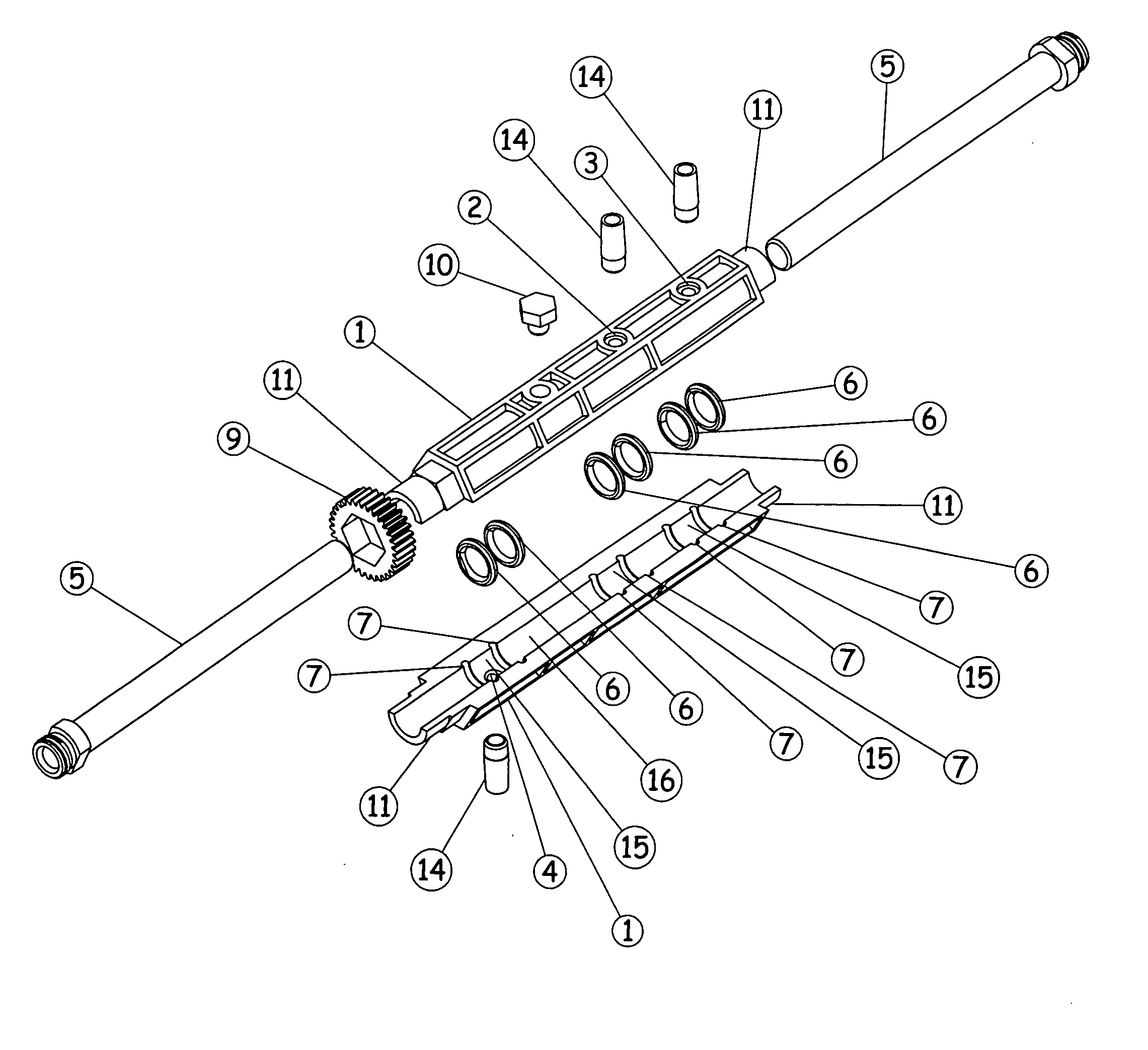
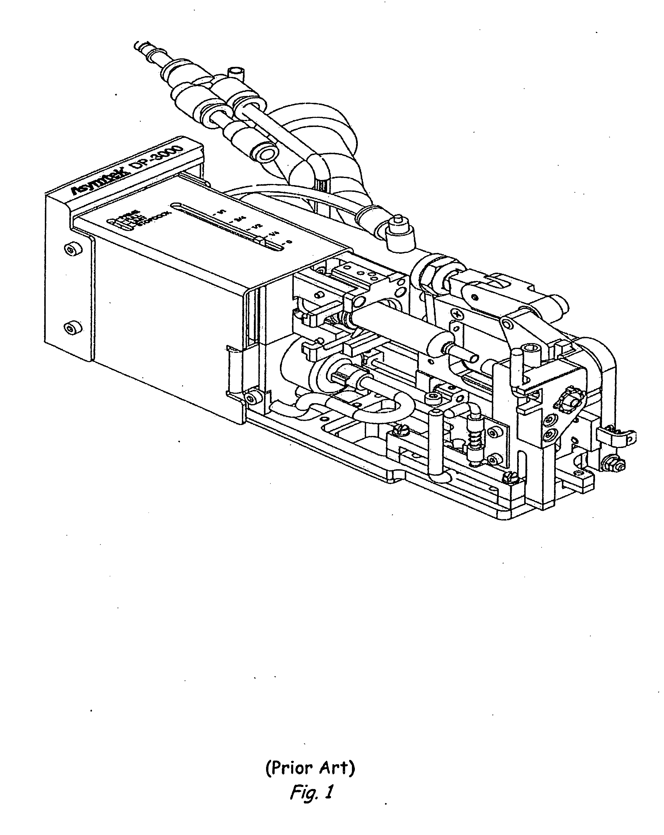
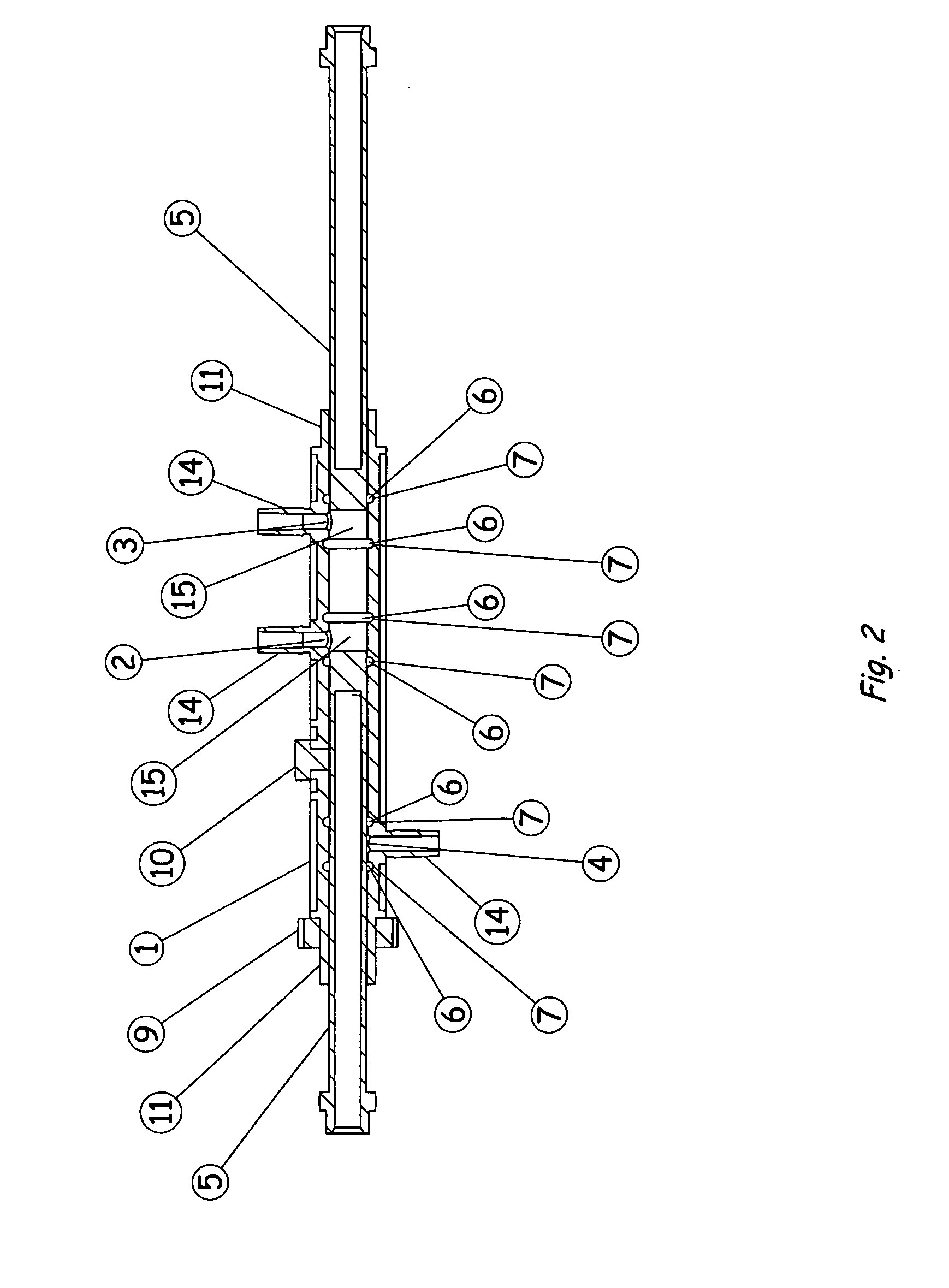
[0054]Referring now to the drawings wherein the showings are for the purpose of illustrating preferred embodiments of the invention only and not for the purpose of limiting it. FIG. 1 Prior Art positive displacement pump is an automated device that moves fluid by filling a cavity with fluid and extruding the fluid through displacement of volume by a cylinder that is pushed into the fluid filled cavity. A seal around the cylinder prevents fluid leakage upward so as to direct fluid downward out the end of the cavity. Fluid is directed through a disposable polycarbonate medical stopcock to a nozzle for deposit onto the work. The stopcock is an essential component of the device. It is used to switch between refill of the chamber and extrusion of fluid out of the cavity. The pump is primed by retracting the cylinder to a position above the seal to enable fluid to flow from an on board reservoir through the stopcock up the chamber and out the pump for the purpose of ejecting air bubbles a...


PUM


Abstract

A novel method of designing a twisting translational pump cartridge by utilizing a polymer shell with moveable cores inserted from each end. The polymer shell contains two perpendicular passages along the top for connection of a prime fluid chamber, a bulk fluid supply chamber and a fluid reservoir. These perpendicular passages and corresponding connection details are arranged in a fashion that is perpendicular to the axis of the polymer shell that comprises the pump cartridge cavity. Directly below at a different relative position also perpendicular to the axis of the pump cartridge cavity is an exit perpendicular passage for extrusion of fluid. The pump cartridge contains no valves or ancillary passages to direct flow between the different machine states of prime, refill, translate and dispense. The states are activated by changing the pitch of the twist or speed to determine relative position of the moveable cores with respect to each passage. Fluid moves by translation within the pump cartridge by filling the cavity volume between the oblate ends of the moveable cores with a liquid and matching the pitch of advancing left moveable core with the retreating pitch of the right moveable core. Both moveable cores can be directed to twist toward one another or one moveable core can remain stationary while the other advances twisting toward it to dispense a liquid.

Description

CROSS REFERENCE TO RELATED APPLICATIONS[0001]This is a continuation of application Ser. No. 11 / 985,652, filed 17 Nov. 2007.FEDERALLY FUNDED RESEARCH[0002]Not ApplicableSEQUENCE LISTING OR PROGRAM[0003]Not ApplicableBACKGROUND OF INVENTION[0004]1. Field of the Invention[0005]This invention pertains to the field of liquid dispensing equipment. More particularly, it pertains to design of a pump that employs a novel method of pumping or extruding a fluid. The pump design is capable of accomplishing this task without the use of valves or redirection of fluid through ancillary pathways. Both cores occupy a polymer shell; each core is inserted from opposite ends, a reservoir and a prime chamber are installed on the topside of the polymer shell. The exit perpendicular passage is directly below and provides for connection of a nozzle or other passage for extrusion of the fluid.[0006]2. Description of the Prior Art[0007]At present there are four general types of pumps used to underfill electr...

Claims


Application Information

Patent Timeline
IPC IPC(8): B67D7/00
CPCF04B3/00F04B19/025F04B13/00F04B7/045
Inventor VERRILLI, BRIAN LEONARD
Owner VERRILLI BRIAN LEONARD
Why Eureka
Try Eureka