Electrical motor/generator drive apparatus and method

a technology of electric motors and motor stops, applied in the direction of motor/generator/converter stoppers, electronic commutators, dynamo-electric converter control, etc., can solve the problems of increasing the cost, weight and complexity of the vehicle, and the cost of current available capacitors b>14/b> that can meet the demanding requirements of hev applications

Active Publication Date: 2011-03-31
UT BATTELLE LLC
View PDF7 Cites 43 Cited by
  • Summary
  • Abstract
  • Description
  • Claims
  • Application Information

AI Technical Summary

Benefits of technology

[0016]Electrical motor/generator drive systems are disclosed. The drive systems include a battery and a DC bus filter capacitor that is connected in parallel with the battery. An inverter having pairs of switches is connected in parallel with the DC bus filter capacitor. One or more motor/generators, defining at least two sets of stator windin

Problems solved by technology

Currently available capacitors 14 that can meet the demanding requirements of HEV application are both costly and bulky.
Further, their ripple current handling capability drops rapidly as the ambient temperature increases.
Thus, a low temperature liquid cooling syst

Method used


Image

  • Electrical motor/generator drive apparatus and method
  • Electrical motor/generator drive apparatus and method
  • Electrical motor/generator drive apparatus and method

Examples


examples

[0048]The following non-limiting Examples serve to illustrate selected embodiments of the invention. It will be appreciated that variations in proportions and alternatives in elements of the components shown will be apparent to those skilled in the art and are within the scope of embodiments of the invention.

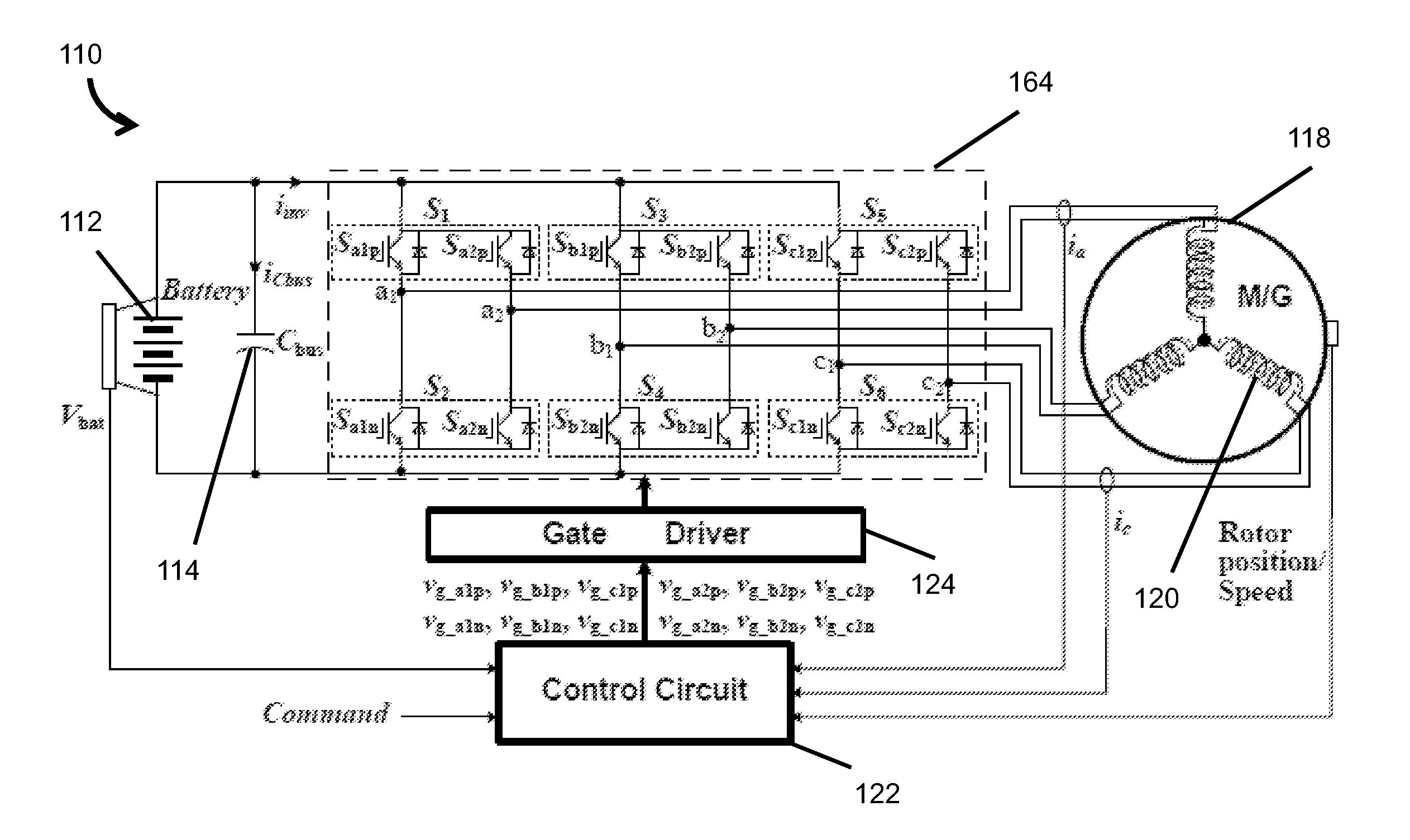
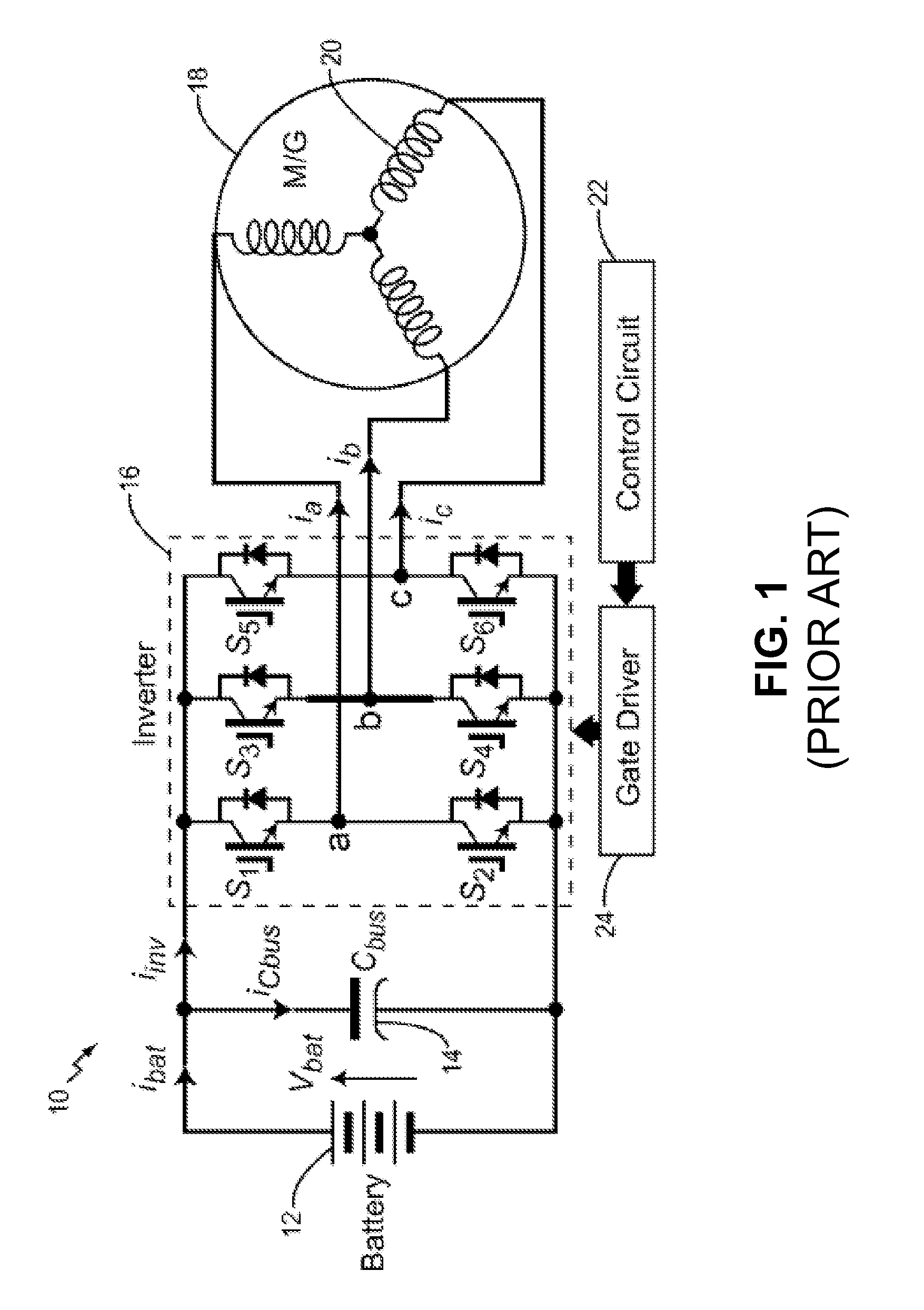
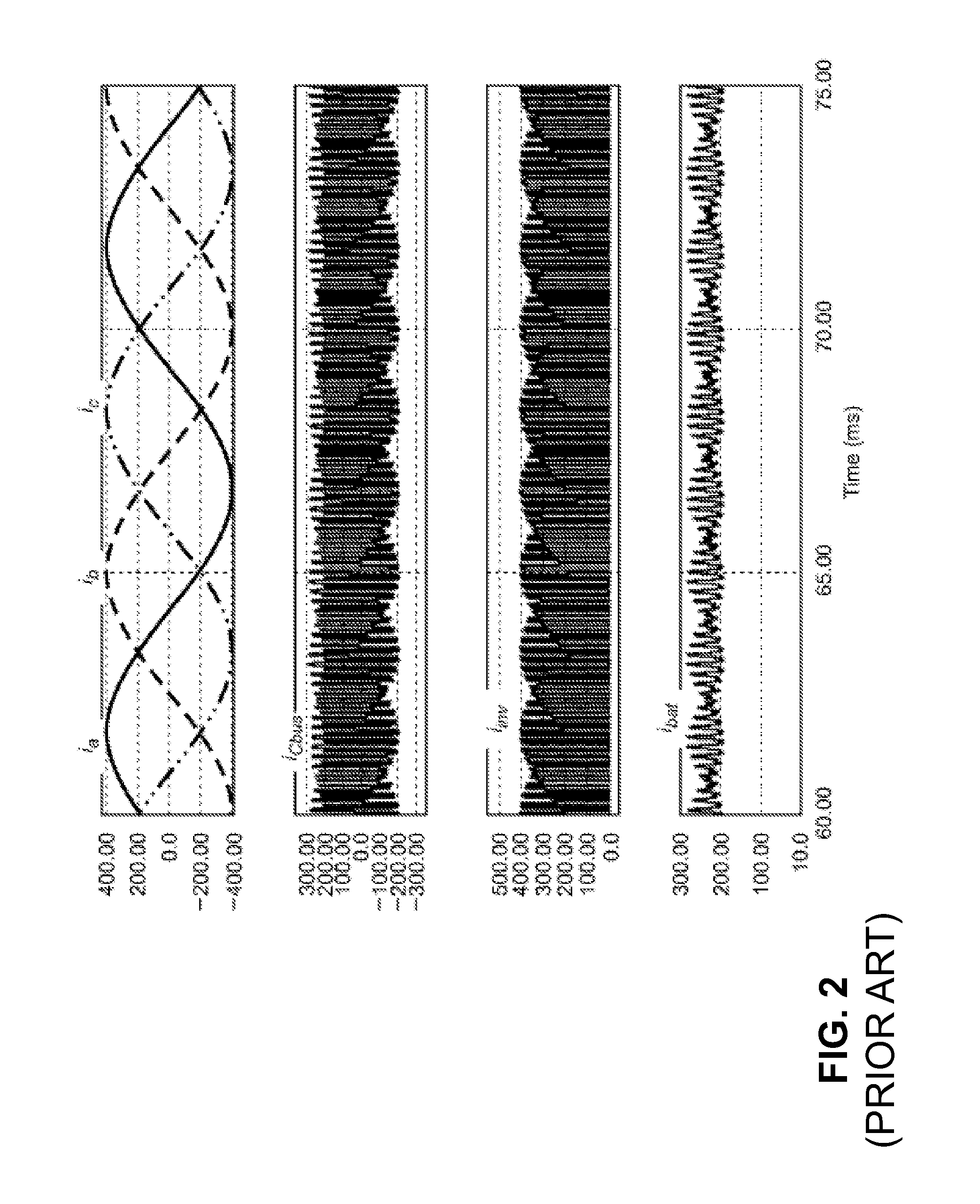
[0049]FIG. 9 is an X-Y plot 900 of capacitor ripple current as a function of motor phase current for a conventional drive system configuration as in FIG. 1 (Curve 902) and a drive system configured in accordance with the embodiment illustrated in FIG. 5 (Curve 904). For purposes of FIG. 9, the two systems were configured to utilize a DC power supply outputting 300V, a 400 μF capacitor, IGBT switches (as described above), and a three-phase induction motor with two sets of Y-connected stator windings, where the neutral nodes of the windings are not directly coupled.

[0050]Control of the IGBT switches was provided using a TMS320F2812 digital signal processor (DSP) manufactured by Te...


PUM


Abstract

The present disclosure includes electrical motor/generator drive systems and methods that significantly reduce inverter direct-current (DC) bus ripple currents and thus the volume and cost of a capacitor. The drive methodology is based on a segmented drive system that does not add switches or passive components but involves reconfiguring inverter switches and motor stator winding connections in a way that allows the formation of multiple, independent drive units and the use of simple alternated switching and optimized Pulse Width Modulation (PWM) schemes to eliminate or significantly reduce the capacitor ripple current.

Description

CROSS-REFERENCE TO RELATED APPLICATIONS[0001]This application claims the benefit of Provisional Application Ser. No. 61 / 245,682 entitled “ELECTRICAL MOTOR / GENERATOR DRIVE APPARATUS AND METHOD”, filed Sep. 25, 2009, which is herein incorporated by reference in its entiretySTATEMENT REGARDING FEDERALLY SPONSORED RESEARCH AND DEVELOPMENT[0002]This invention was made with government support under Contract No. DE-AC05-00OR22725 awarded by the U.S. Department of Energy. The government has certain rights in the invention.THE NAMES OF THE PARTIES TO A JOINT RESEARCH AGREEMENT[0003]None.BACKGROUND OF THE INVENTION[0004]1. Field of the Invention[0005]This disclosure relates to electric motors and more specifically to electrical motor drive methods and apparatuses.[0006]2. Description of the Related Art[0007]The use of electric vehicles (EVs) has been promoted in recent years as an effective way to reduce crude oil consumption and emissions of harmful pollutants and green-house gasses. EVs bro...

Claims


Application Information

Patent Timeline
IPC IPC(8): H02P6/14
CPCH02P5/74H02P6/165H02P2207/01H02P27/08H02P25/22H02P6/17
Inventor SU, GUI JIA
Owner UT BATTELLE LLC
Why Eureka
Try Eureka