
Auto-tune of a control system based on frequency response

a technology of frequency response and control system, applied in adaptive control, process and machine control, instruments, etc., can solve the problems of insufficient stability margins, difficult tuning of control laws, and high cost of dsa units, so as to reduce the amount of motion and save time.

Active Publication Date: 2011-03-31
KOLLMORGEN CORP
View PDF23 Cites 24 Cited by
  • Summary
  • Abstract
  • Description
  • Claims
  • Application Information

AI Technical Summary

Benefits of technology

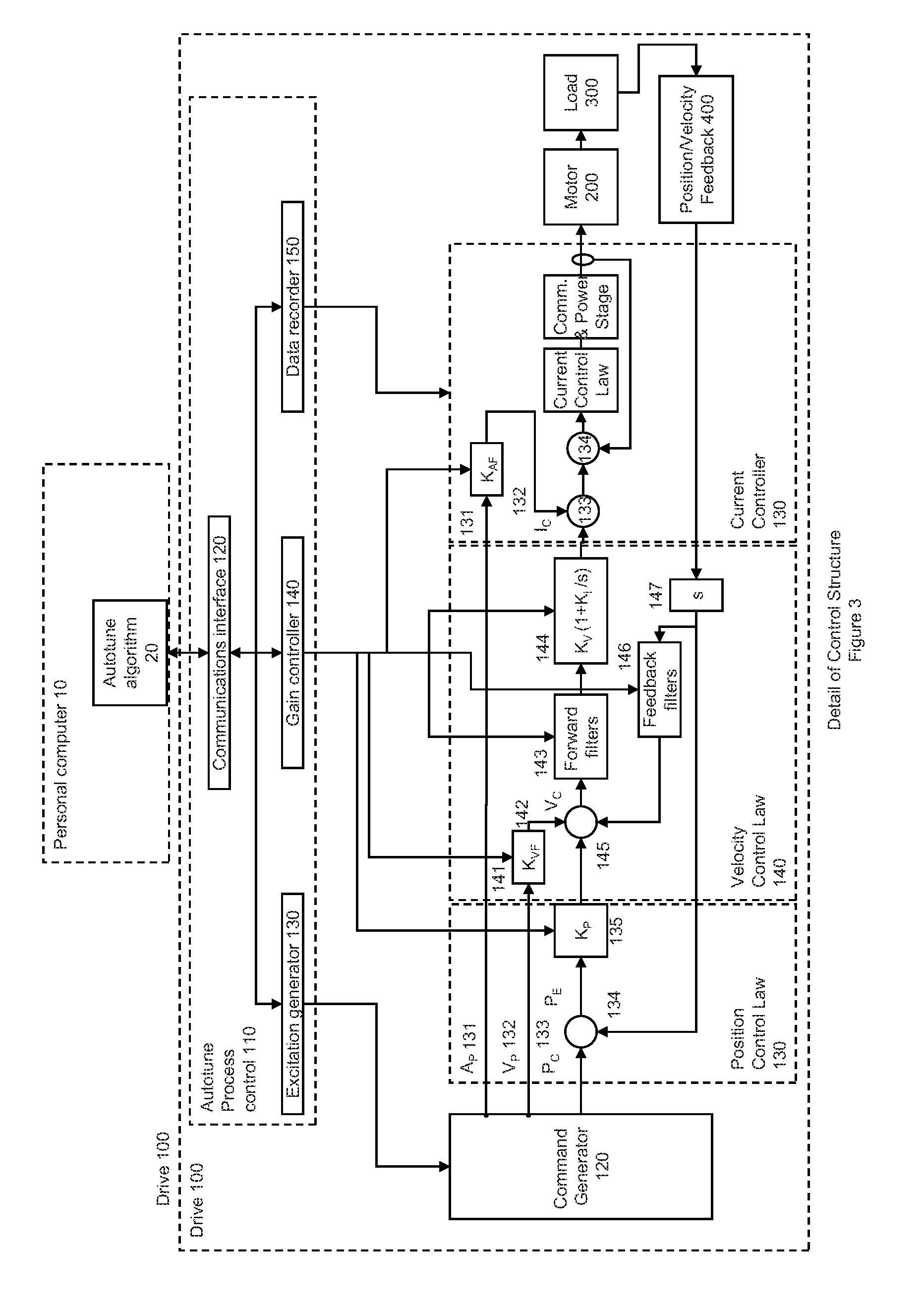
[0021]In a further embodiment, the proposed tuning parameters can be initially tuned for stable operation with a low response to allow the system to be excited so that frequency response data can be gathered for tuning the controller by applying a low frequency sinusoid to the control system to determine a motor acceleration constant of a motor and a load. By simulating the system based on the motor acceleration constant, an initial set of tuning parameters can be calculated. Tuning parameters can include one or more of proportional, integral and derivative gains of the controller or one or more of filters. The tuning parameters can also include a proportional controller for the position controller and another proportional, integral controller for the velocity. Applying tuning at this stage will reduce the amount of motion in subsequent tests, described below. This initial tuning can be skipped when the reduction of motion in subsequent tests is not required of if the user wishes to skip this step (ex. to save time), without loss of ultimate tuning accuracy.

Problems solved by technology

Control laws that are poorly tuned either act too aggressively or too sluggishly, or with insufficient margins of stability.
When the uncertainty in the disturbance or process dynamic characteristics is large, the tuning of a control law is often difficult.
However, while manual tuning of a controller is possible, it is often tedious and results are often non-optimal
A DSA unit, however, is relatively expensive.
Moreover, the number of points available to the DSA for injecting test signals is often fewer than desired.
As a result, the use of such equipment is usually limited to the research laboratory and is not generally available at the user site.

Method used


Image

  • Auto-tune of a control system based on frequency response
  • Auto-tune of a control system based on frequency response
  • Auto-tune of a control system based on frequency response

Examples


Embodiment Construction

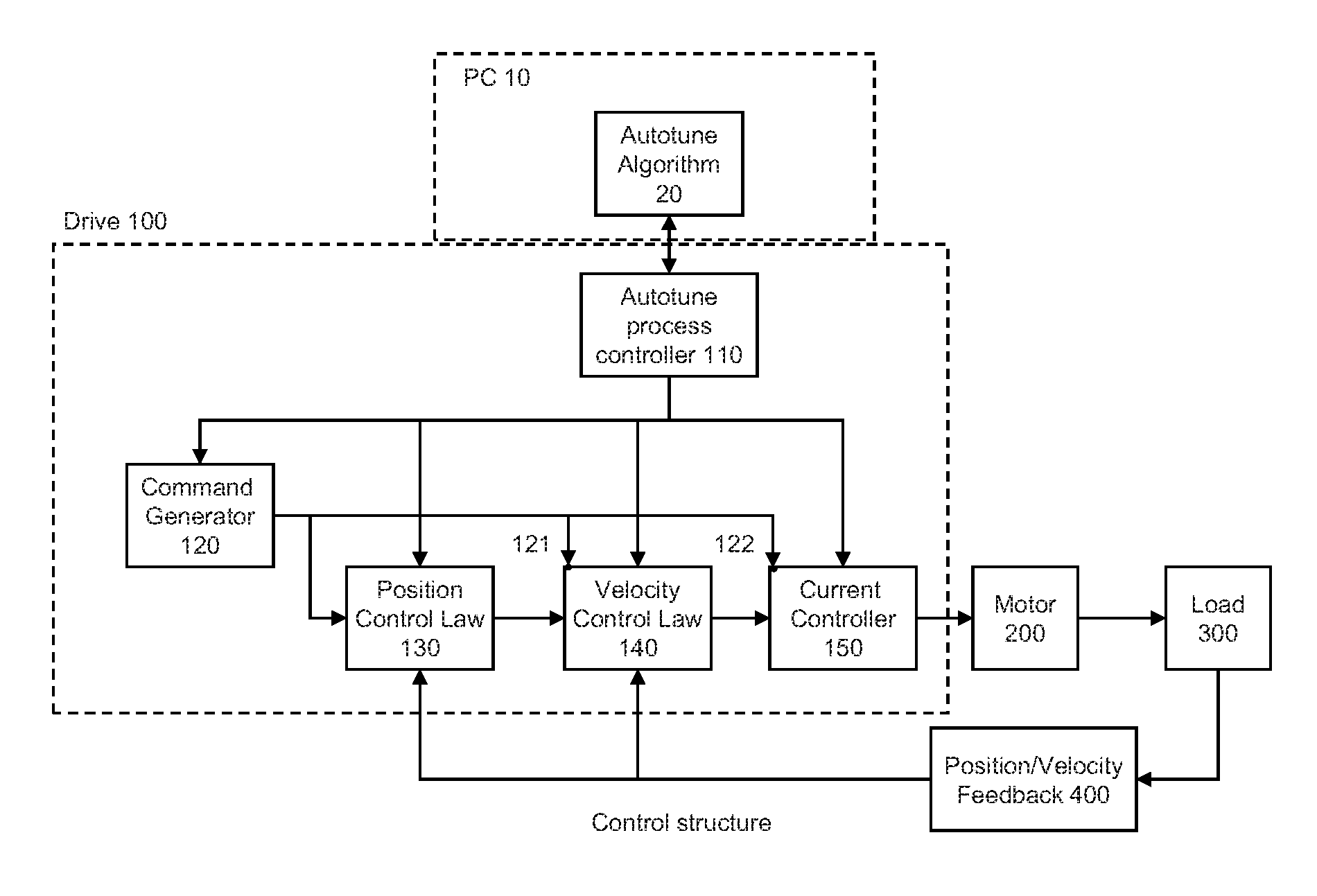
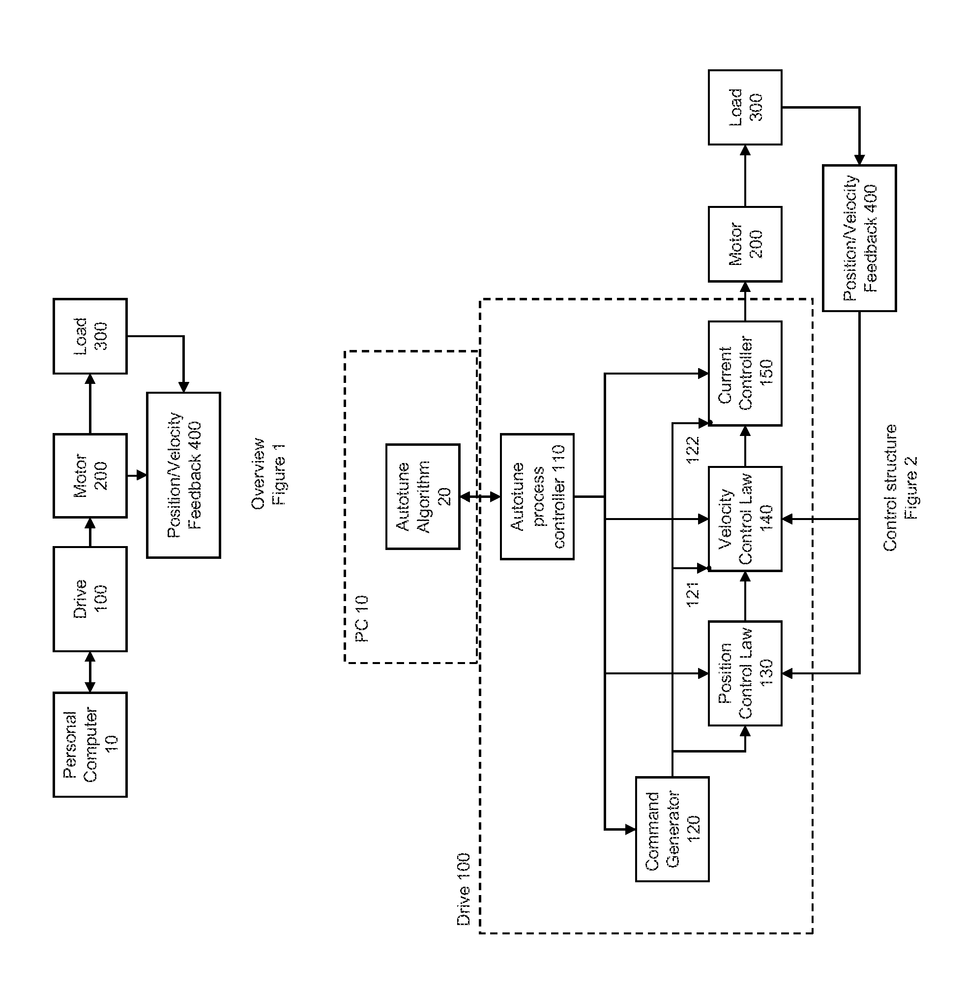
[0038]FIG. 1 illustrates an overview of a motor control system in which an auto-tuning system is implemented. The motor control system includes a drive 100, a motor 200, driving a load 300 and a position and / or velocity measuring device 400. It should be understood that there are many variations of the feedback structure including a single position sensor on the motor, a single position sensor on the load, a combination of a position sensor on the motor and another on the load, all of which are included herein. It should be understood that velocity can be measured directly on the motor, the load or both rather than being calculated from a position sensor. This configuration is also included herein. It should be understood that position and velocity can be calculated using “sensorless” techniques which use the characteristics of the motor to sense position and velocity. This configuration is also included herein.

[0039]FIG. 2 shows a view of the control structure. Command generator 12...


PUM


Abstract

A method and system of determining tuning parameters for use in tuning a controller used in a process control loop for a motor and associated load. The method includes providing tuning parameters, applying an excitation test signal, receiving frequency response data to determine phase and gain margins, creating an instability region defined by a bounded area that connects the phase and gain margins with a boundary on a gain vs. phase plot, assigning and applying cost functions, and computing stability determinations.

Description

CROSS-REFERENCE TO RELATED APPLICATION[0001]This application claims the benefit of U.S. Provisional Application Nos. 61 / 246,677, filed Sep. 29, 2009 and 61 / 256,583, filed Oct. 30, 2009, incorporated herein by reference.FIELD OF THE INVENTION[0002]This invention relates to a method and system for an auto-tuning of a motor controller. More particularly, the present invention relates to a method and system by which a controller of a control system for a motor and associated load is automatically tuned based on frequency response.BACKGROUND OF THE INVENTION[0003]A control system generally includes a controller and a plant (e.g., motor driving a load) to be controlled which is connected to the controller through a feedback loop. In operation, the plant is controlled by the output of the controller and the plant output is fed back via a feedback path where it is subtracted from a reference input to form an error signal. This error signal is processed by the controller to generate a modifi...

Claims


Application Information

Patent Timeline
Patent Type & Authority Applications(United States)
IPC IPC(8): G05B13/04
CPCG05B13/042
Inventor ELLIS, GEORGEBREWSTER, ERIK
Owner KOLLMORGEN CORP
Learn More