Vehicle charger safety system and method

a safety system and charger technology, applied in the field of charging vehicles, can solve the problems of limited use of wireless charging systems for vehicle charging, limited commercial deployment of wireless vehicle charging apparatus, and large amount of energy that needs to be transferred

Inactive Publication Date: 2011-03-31
WITRICITY CORP
View PDF122 Cites 487 Cited by
  • Summary
  • Abstract
  • Description
  • Claims
  • Application Information

AI Technical Summary

Benefits of technology

[0011]A wireless vehicle charger includes subsystems to address safety concerns. A detection subsystem determines whether there is a safety issue.

Problems solved by technology

To date, use of wireless systems for vehicle charging, such as in charging stations for fully electric or hybrid automobiles, has been limited due to various difficulties.
For instance, efficiency in energy transfer, physical proximity / alignment of supply and device components and related factors have all posed challenges limiting commercial deployment of wireless vehicle charging apparatus.
The amount of energy that needs to be transferred when charging an electric vehicle is significant and to do so in a reasonable timeframe requires significant levels of power transfer.
For wired charging systems, numerous safety issues need to be considered, such as cut cables, abraded insulation, sparking connectors in areas with potentially flammable materials, heat build-up from connections that are dirty or have otherwise developed up some electrical resistance, cable breakaways due to operator failure to set parking brakes, etc.
Although these systems obviate many of the safety concerns of wired vehicle charging systems, some safety issues still remain and they may be quite different than those in either wired vehicle charger systems or in smaller wireless systems, such as those used to charge consumer devices (e.g., cell phones and laptop computers).
One particular area of concern with vehicle charging is the potential overheating of materials in the area of the charging system.
For example, a metal object between a vehicle charger's source resonator and an automobile's device resonator may become too hot to touch as a result of eddy currents that are induced in the object.

Method used


Image

  • Vehicle charger safety system and method
  • Vehicle charger safety system and method
  • Vehicle charger safety system and method

Examples


Embodiment Construction

[0023]As described above, this disclosure relates to wireless vehicle chargers using coupled resonators. Extensive discussion of systems using such resonators is provided, for example, in commonly owned U.S. patent application Ser. No. 12 / 613,686 published on May 6, 2010 as US 2010010909445 and entitled “Wireless Energy Transfer Systems,” and incorporated herein by reference in its entirety as if fully set forth herein.

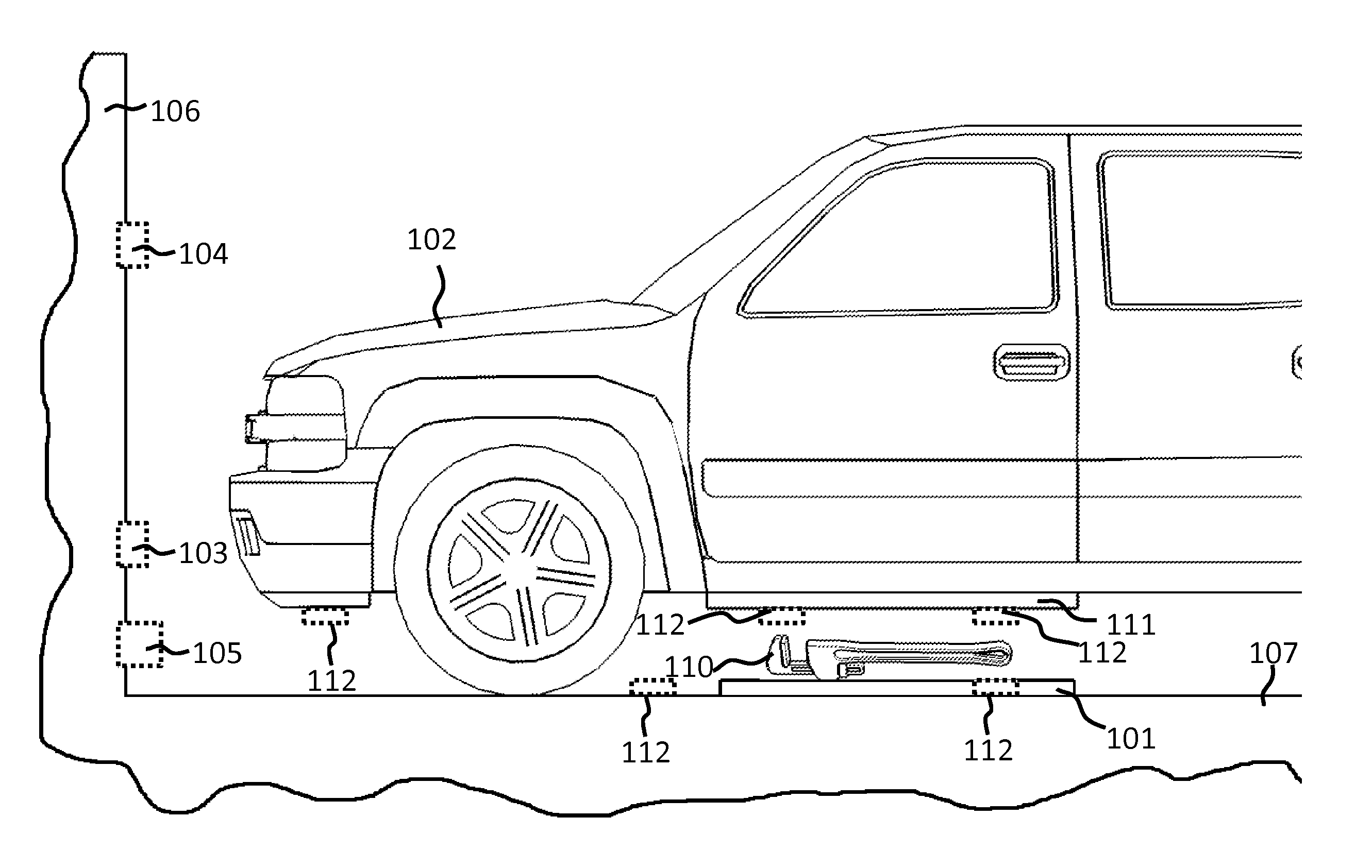
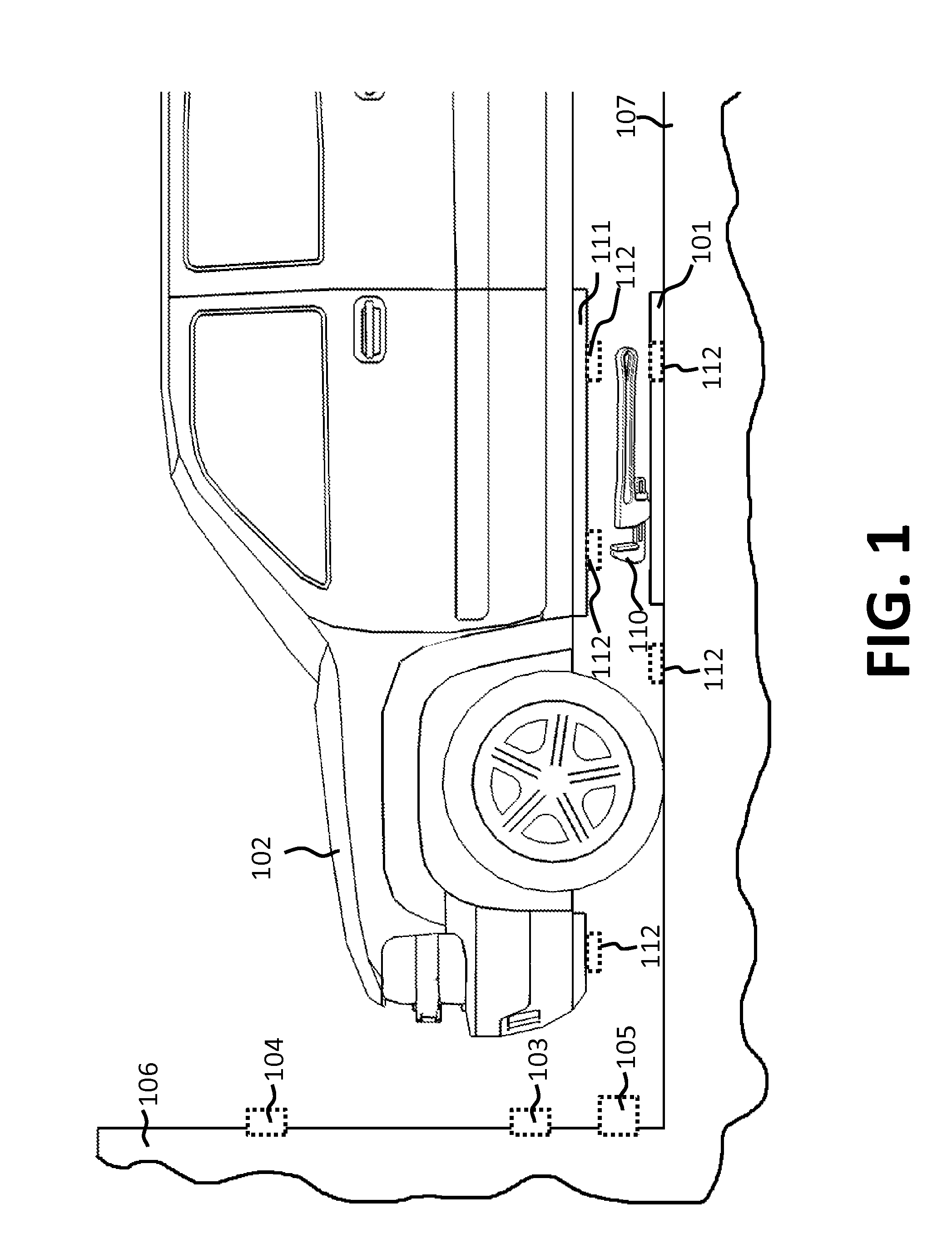
[0024]Referring now to FIG. 1, a charging source resonator 101 is integrated with a garage floor 107 so as to provide wireless charging to an automobile 102. In one embodiment, source resonator 101 is embedded in floor 107. In a second embodiment, resonator 101 is fixed on top of floor 107, such as by a plate bolted to floor 107. In a third embodiment, resonator 101 is implemented as a mat laid on top of floor 107. Resonator 101 is part of a wireless vehicle charging system, the other components of which are not explicitly illustrated here. For clarity in this disclos...


PUM


Abstract

Wireless vehicle charger safety systems and methods use a detection subsystem, a notification subsystem and a management subsystem. The detection subsystem identifies a safety condition. The notification subsystem provides an indication of the safety condition. The management subsystem addresses the safety condition. In particular, undesirable thermal conditions caused by foreign objects between a source resonator and a vehicle resonator are addressed by sensing high temperatures, providing a warning and powering down a vehicle charger, as appropriate for the environment in which the charger is deployed.

Description

CROSS-REFERENCE TO RELATED APPLICATIONS[0001]This application is a continuation-in-part and claims the benefit of the following commonly owned U.S. patent applications, the contents of which are incorporated herein by reference: copending U.S. patent application Ser. No. 12 / 613,686 published on May 6, 2010 as US 2010010909445 and entitled “Wireless Energy Transfer Systems,” which is a continuation of copending U.S. patent application Ser. No. 12 / 567,716 published on Jun. 10, 2010 as US 20100141042 and entitled “Wireless Energy Transfer Systems;” U.S. patent application Ser. No. 12 / 721,118, filed Mar. 10, 2010 and published on ______ as U.S. Ser. No. ______ and entitled “Wireless Energy Resonator Enclosures,” which is a continuation-in-part of U.S. patent application Ser. No. 12 / 705,582, filed Feb. 13, 2010; and U.S. patent application Ser. No. 12 / 770,137, filed Apr. 29, 2010 and published on ______ as U.S. Ser. No. ______ and entitled “Wireless Energy Transfer Between a Source and a...

Claims


Application Information

Patent Timeline
Patent Type & Authority Applications(United States)
IPC IPC(8): H02J7/02
CPCB60L3/00B60L11/182B60L11/1838B60L2260/46H02J5/005H03H7/40Y02T90/121Y02T90/122Y02T90/128Y02T90/14Y02T90/163H02J7/025B60L2200/26Y02T10/7005B60L53/124B60L53/62B60L53/126H02J50/90H02J50/12H02J50/60H02J50/80B60L53/12B60L53/60Y02T10/7072Y02T10/70Y02T90/12Y02T90/16
Inventor HALL, KATHERINE L.KESLER, MORRIS P.FIORELLO, RONSCHATZ, DAVID A.KULIKOWSKI, KONRAD J.SOLJACIC, MARIN
Owner WITRICITY CORP
Why Eureka
Try Eureka