
Image displaying apparatus, image display observing system and image displaying method

a technology of image display and observing system, applied in the field of image display apparatus, image display observing system and image display method, can solve the problems of lowering the luminance of the image, user may not recognize vivid video with high luminance, etc., and achieve optimal adjustment of image color and restrict luminance from lowering

Active Publication Date: 2011-03-31
SATURN LICENSING LLC
View PDF14 Cites 25 Cited by
  • Summary
  • Abstract
  • Description
  • Claims
  • Application Information

AI Technical Summary

Benefits of technology

[0006]In light of the foregoing, it is desirable to provide a novel and improved image displaying apparatus, image display observing system and image displaying method capable of restricting a decrease in luminance and optimally adjusting the color of the image.
[0020]According to the embodiment of the present invention, it is possible to restrict luminance from lowering and to optimally adjust an image color.

Problems solved by technology

However, when the color temperature is corrected at the display side, color temperatures of the colors other than the desired color temperature need to be adjusted by restricting luminance.
In this case, the luminance of the image is lowered in accordance with the adjustment of the color temperature, and there will occur an issue that a user may not recognize a vivid video with high luminance.

Method used


Image

  • Image displaying apparatus, image display observing system and image displaying method
  • Image displaying apparatus, image display observing system and image displaying method
  • Image displaying apparatus, image display observing system and image displaying method

Examples


Embodiment Construction

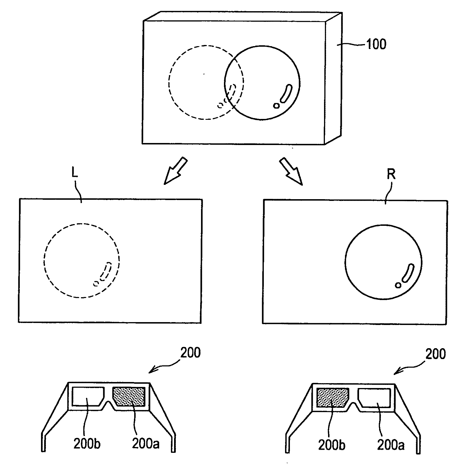
[0028]Hereinafter, a preferred embodiment of the present invention will be described in detail with reference to the appended drawings. Note that, in this specification and the appended drawings, structural elements that have substantially the same function and structure are denoted with the same reference numerals, and repeated explanation of these structural elements is omitted.

[0029]The explanation will be made in the following order.

[0030](1) Structure example of system

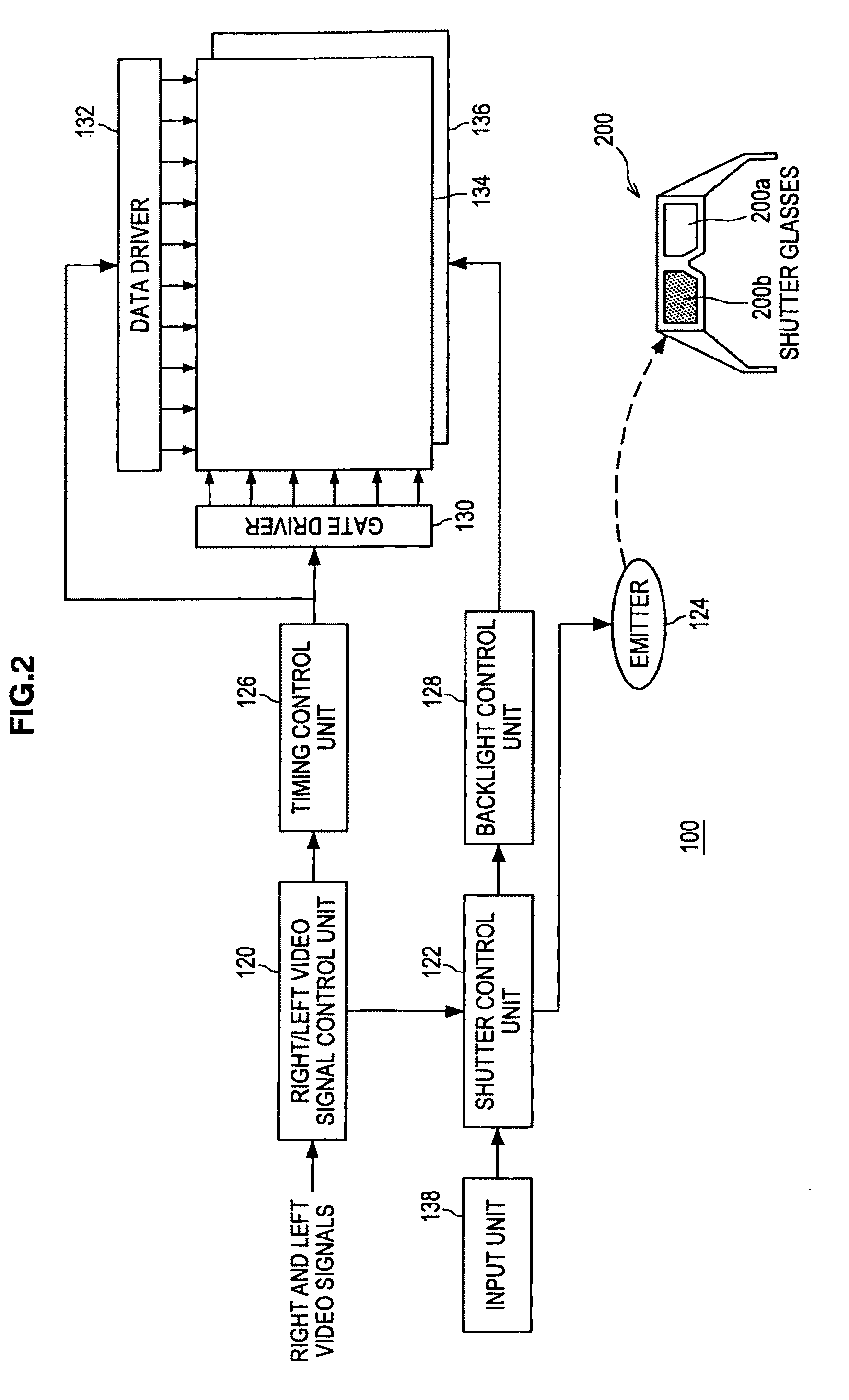
[0031](2) Structure example of image displaying apparatus

[0032](3) Example of double writing according to the embodiment

[0033](4) Synchronization Between Backlight and Shutter Opening / Closing

[0034](5) Color temperature adjustment using difference in response characteristics for each color in liquid crystal

[0035](6) Control and others of backlight OFF period

[0036](7) Application to system for periodically displaying multiple different images

[(1) Structure Example of System]

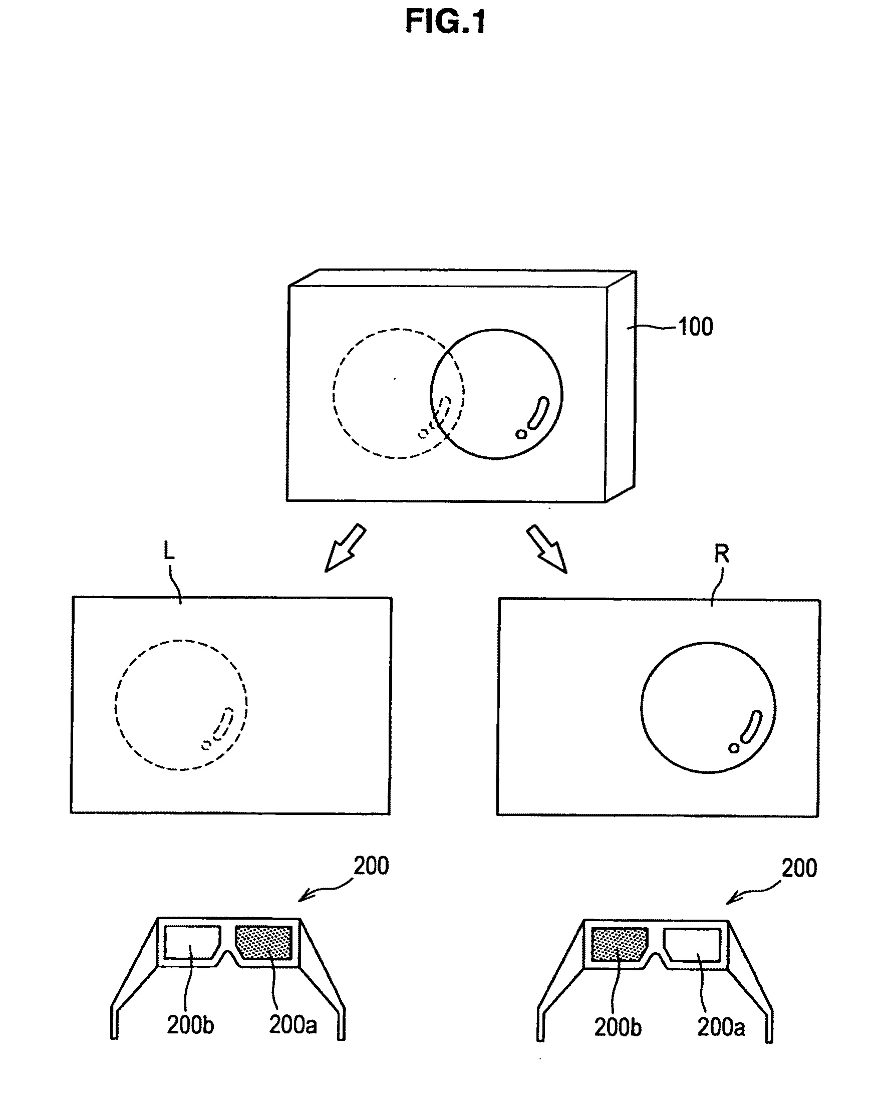
[0037]FIG. 1 is a schematic diagram showin...


PUM


Abstract

An image displaying apparatus includes a signal control unit for receiving an input image signal and converting the signal into a signal for alternately displaying a right-eye image and a left-eye image, display panel into which the signal converted in the signal control unit is input for the right-eye image and the left-eye image, a surface light source for illuminating the display panel from its back, a shutter control unit for generating a timing signal indicating a period in which the right-eye and left-eye shutters are opened for a pair of viewing glasses with the right-eye and left-eye shutters, and for relatively changing the shutter-opened period for the emission timing of the surface light source, and a surface light source control unit for emitting the surface light source in a shorter period than the shutter-opened period in response to the switching between the right-eye image and the left-eye image.

Description

BACKGROUND OF THE INVENTION[0001]1. Field of the Invention[0002]The present invention relates to an image displaying apparatus, an image display observing system and an image displaying method.[0003]2. Description of the Related Art[0004]In related art, as described in Japanese Patent Application Laid-Open Nos. 9-138384, 2000-36969, and 2003-45343 for example, there is known a method for alternately supplying a left-eye image and a right-eye image, both of which have a disparity, to a display at a predetermined period and observing the images with a pair of glasses including liquid crystal shutters driven in synchronization with the predetermined period.SUMMARY OF THE INVENTION[0005]A typical 2D television receiver includes a display mode or a function capable of changing an image color (color temperature) through user setting, and naturally a similar function is needed for a 3D image displaying apparatus. However, when the color temperature is corrected at the display side, color t...

Claims


Application Information

Patent Timeline
Patent Type & Authority Applications(United States)
IPC IPC(8): H04N13/04
CPCH04N13/00H04N13/0422H04N13/0497H04N13/0438H04N13/0429H04N13/341H04N13/324H04N13/332H04N13/398
Inventor NAKAHATA, YUJI
Owner SATURN LICENSING LLC
Learn More