
Vehicle device

a technology for vehicles and drivers, applied in the field of vehicles, can solve the problems of reducing the reliability of drivers for travel assistance, unable to control vehicles, restricting the decrease of driver's reliability for travel assistance, etc., and achieve the effect of restricting the decrease of driver's reliability

Active Publication Date: 2020-03-03
DENSO CORP
View PDF14 Cites 0 Cited by
  • Summary
  • Abstract
  • Description
  • Claims
  • Application Information

AI Technical Summary

Benefits of technology

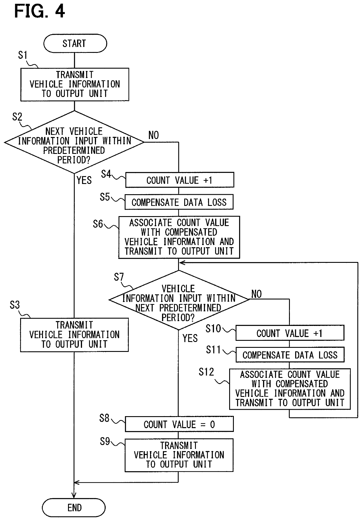
This solution restricts the use of potentially inaccurate assistive data for travel assistance, maintaining driver reliability by ensuring accurate vehicle control and preventing inappropriate vehicle control based on the compensation implementation value.

Problems solved by technology

There is a possibility that the vehicle cannot be controlled in accordance with an actual vehicle situation depending on the accuracy of interpolated data, and driver's reliability for the travel assistance is decreased.
As a result, it is possible to restrict the decrease of driver's reliability for the travel assistance.

Method used


Image

  • Vehicle device
  • Vehicle device
  • Vehicle device

Examples


first embodiment

[0019]3>

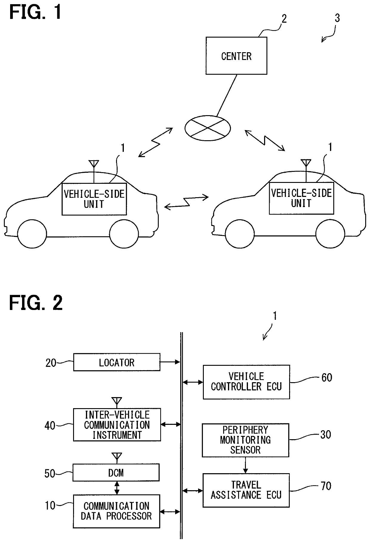
[0020]The description below explains a first embodiment of the present disclosure with reference to the accompanying drawings. As illustrated in FIG. 1, a travel assistance system 3 includes a vehicle-side unit 1 and a center 2. The vehicle-side unit 1 is mounted on each of a plurality of vehicles.

[0021]The vehicle-side unit 1 communicates with the vehicle-side unit 1 mounted on a nearby vehicle around a subject vehicle and communicates with the center 2. The center 2 is available as a server, for example. The center 2 acquires vehicle information transmitted from the vehicle-side unit 1 of a certain vehicle via a public telecommunication network and transfers the vehicle information to the vehicle-side unit 1 of another vehicle. The travel assistance system 3 allows the vehicle-side units 1 to directly communicate with each other or to indirectly communicate with each other via the center 2.

[0022]Direct communication between the vehicle-side units 1 (hereinafter referred to...

second embodiment

[0072]The first embodiment provides the configuration to avoid using the vehicle information for the travel assistance depending on count values associated with the vehicle information about the nearby vehicle, but is not limited thereto. For example, there may be a configuration (hereinafter referred to as a second embodiment) that changes automation levels of the automatic driving depending on count values associated with the vehicle information about the nearby vehicle.

[0073]The description below explains the second embodiment of the present disclosure with reference to the accompanying drawings. The travel assistance system 3 according to the second embodiment equals the travel assistance system 3 according to the first embodiment except that the travel assistance ECU 70 is replaced by a travel assistance ECU 70a.

[0074]The travel assistance ECU 70a will be described with reference to FIG. 7. As illustrated in FIG. 7, the travel assistance ECU 70a includes the travel environment...


PUM


Abstract

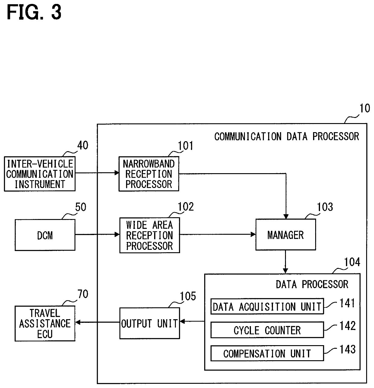
A vehicle device is used for a vehicle and includes a data acquisition unit, a compensation unit, and an output unit. The data acquisition unit acquires data successively transmitted from outside a subject vehicle via communication. The compensation unit compensates a data loss resulting from unsuccessfully acquiring of data in the data acquisition unit by using data already acquired by the data acquisition unit and generates assistive data used for travel assistance of the subject vehicle. The compensation unit associates with the assistive data a compensation implementation value indicating an implementation of the compensation. The output unit outputs the assistive data associated with the compensation implementation value to a travel assistance device for performing the travel assistance when the compensation unit generates the assistive data by compensating the data loss. Accordingly, decrease of driver's reliability for travel assistance using data acquired through communication is restricted.

Description

CROSS REFERENCE TO RELATED APPLICATIONS[0001]This application is a U.S. National Phase Application under 35 U.S.C. 371 of International Application No. PCT / JP2017 / 006450 filed on Feb. 22, 2017 and published in Japanese as WO / 2017 / 159237 A1 on Sep. 21, 2017. This application is based on and claims the benefit of priority from Japanese Patent Application No. 2016-055972 filed on Mar. 18, 2016. The entire disclosures of all of the above applications are incorporated herein by reference.TECHNICAL FIELD[0002]The present disclosure relates to a vehicle device that processes data acquired through communication.BACKGROUND ART[0003]Patent Literature 1 discloses a technology that successively acquires vehicle data through communication, performs predetermined arithmetic processing on the acquired data, and generates output data to control a vehicle. Patent Literature 1 further discloses a technology that uses linear interpolation to interpolate lost data, if any, in the successively acquired ...

Claims


Application Information

Patent Timeline
Patent Type & Authority Patents(United States)
IPC IPC(8): B60W30/12B60W30/09B60W30/16G08G1/09G08G1/16H04L1/00B60W40/04G08G1/0967
CPCB60W30/12B60W40/04G08G1/167G08G1/09H04L1/00B60W30/16B60W30/09H04L1/0033B60W2556/50B60W2555/60G08G1/096775B60W2420/42G08G1/096791G08G1/164G08G1/163B60W50/045B60W50/02B60W2556/20B60W60/0053B60W60/0059B60W2420/403
Inventor SOGABE, HARUHIKO
Owner DENSO CORP
Learn More