Plasma processing apparatus
a processing apparatus and plasma technology, applied in the direction of coating, coating, chemical vapor deposition coating, etc., can solve the problems of plasma within the accommodating compartment falling into an unstable state, plasma treatment characteristics may change, and so as to reduce the value of dc current
- Summary
- Abstract
- Description
- Claims
- Application Information
AI Technical Summary
Benefits of technology
Problems solved by technology
Method used
Image
Examples
example 1
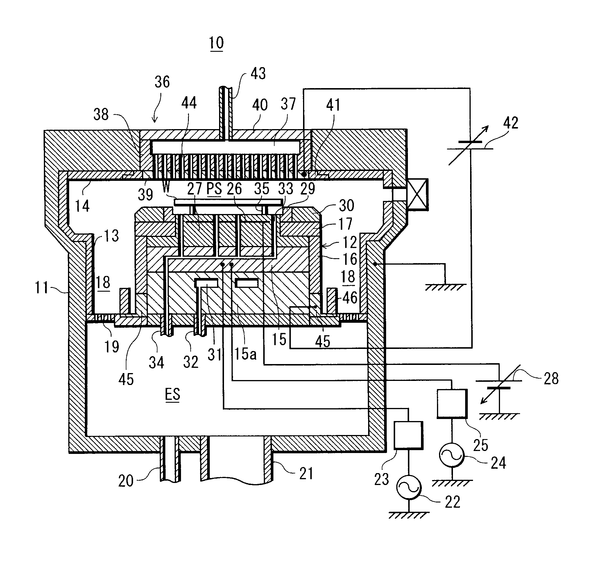
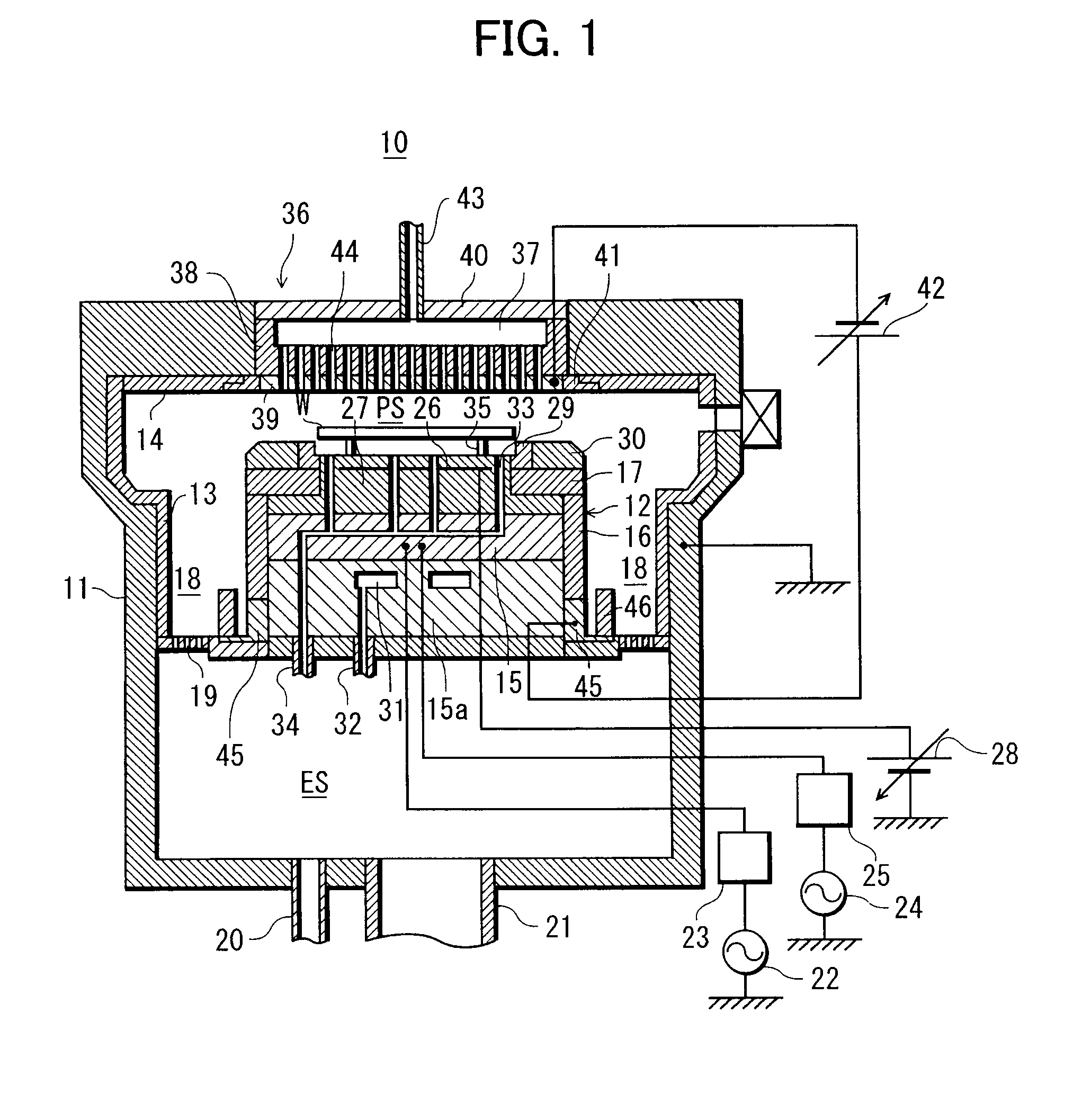
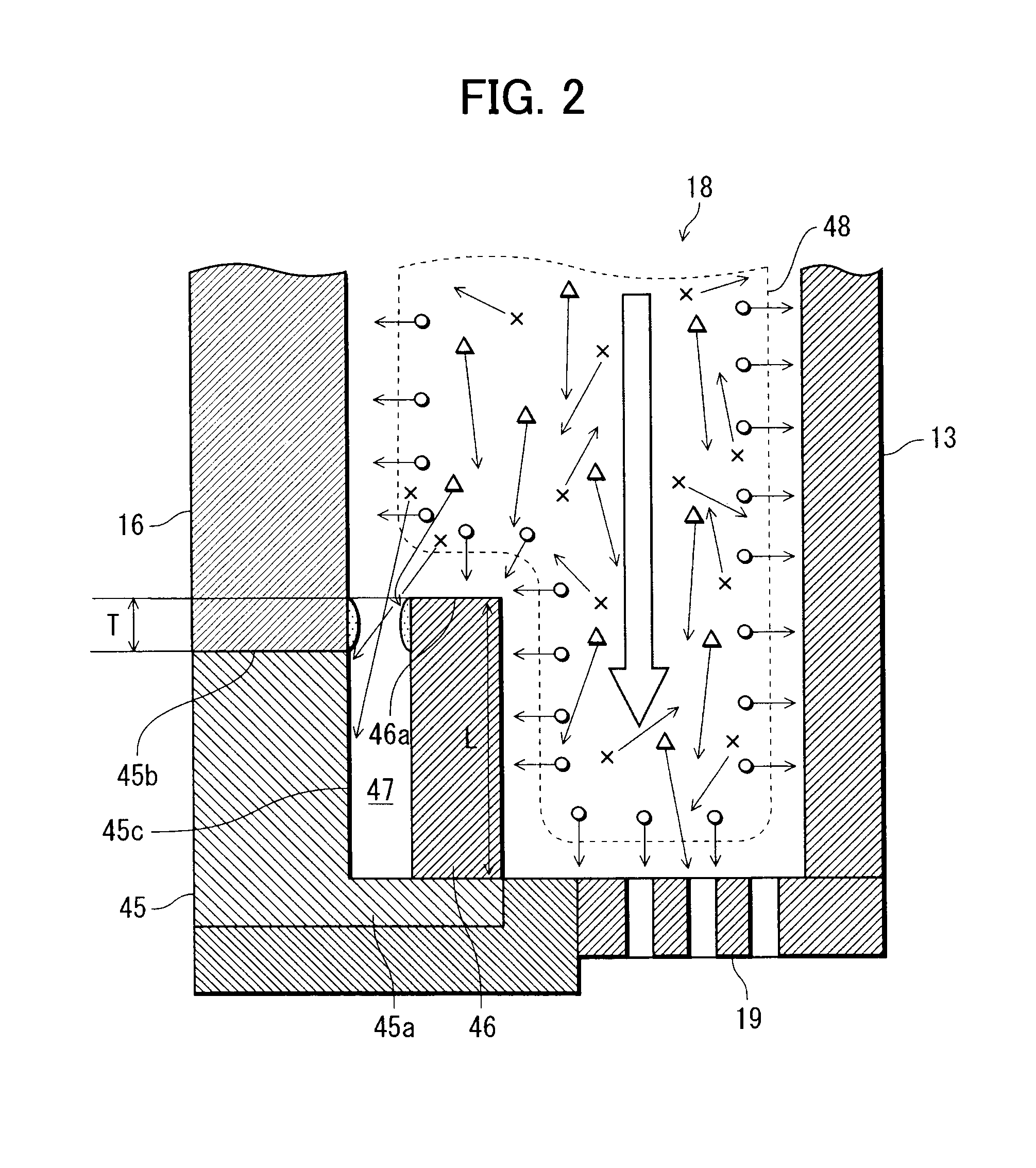
[0078]In the plasma processing apparatus 10, a gap “t” between the ground electrode surface 45c of a grounding ring 45 and a shielding member 46 was set to 2.5 mm, and the amount of protrusion “T” of the edge 46a of the shielding member 46 on the opening side thereof from the edge 45b of the grounding ring 45 on the opening side thereof (see FIG. 2—hereinafter simply referred to as the “protruding amount “T” of the shielding member 46”) was set to 0 mm.
[0079]After that, an etching treatment on a wafer W was repeated in the plasma processing apparatus 10. In each case of etching treatment, a DC current flowing through a processing space PS was measured and the measured values of the DC current were shown by “X” in the graph of FIG. 4. Then, a calculation was made of an approximate expression of the rate of decrease in the value of the DC current (hereinafter simply referred to as the “decrease rate”) for Example 1 in the graph of FIG. 4, thus obtaining Equation (1) shown below:
DC cur...
example 2
[0080]In a plasma processing apparatus 10, a gap “t” was set to 3.5 mm and the protruding amount “T” of a shielding member 46 was set to 3.0 mm.
[0081]After that, an etching treatment on a wafer W was repeated in the plasma processing apparatus 10, as in Example 1. In each case of etching treatment, a DC current flowing through a processing space PS was measured and the measured values of the DC current were shown by “Δ” in the graph of FIG. 4. Then, a calculation was made of an approximate decrease rate expression for Example 2, thus obtaining Equation (2) shown below
DC current value=−6.04×10⁻⁶×number of treated wafers+1.39 (2)
[0082]where, the term “−6.04×10⁻⁶” corresponds to the decrease rate (degradation rate).
example 3
[0086]In a plasma processing apparatus 10, a gap “t” was set to 4.0 mm and the protruding amount “T” of a shielding member 46 was set to 3.0 mm.
[0087]After that, an etching treatment on a wafer W was repeated in the plasma processing apparatus 10, as in Example 1. In each case of etching treatment, a DC current flowing through a processing space PS was measured and the measured values of the DC current were shown by “□” in the graph of FIG. 5.
PUM
| Property | Measurement | Unit |
|---|---|---|
| aspect ratio | aaaaa | aaaaa |
| thickness | aaaaa | aaaaa |
| atmospheric pressure | aaaaa | aaaaa |
Abstract
Description
Claims
Application Information
 - R&D
- Intellectual Property
- Life Sciences
- Materials
- Tech Scout
- Unparalleled Data Quality
- Higher Quality Content
- 60% Fewer Hallucinations
Browse by: Latest US Patents, China's latest patents, Technical Efficacy Thesaurus, Application Domain, Technology Topic, Popular Technical Reports.
© 2025 PatSnap. All rights reserved.Legal|Privacy policy|Modern Slavery Act Transparency Statement|Sitemap|About US| Contact US: help@patsnap.com


