
Video Coder Providing Implicit Coefficient Prediction and Scan Adaptation for Image Coding and Intra Coding of Video

a video coder and coefficient prediction technology, applied in the field of video coders providing implicit coefficient prediction and scan adaptation for image coding and intra-coded video, can solve problems such as lossless processing

Inactive Publication Date: 2011-03-31
AT&T INTPROP I L P
View PDF54 Cites 37 Cited by
  • Summary
  • Abstract
  • Description
  • Claims
  • Application Information

AI Technical Summary

Problems solved by technology

This process is lossless.

Method used


Image

  • Video Coder Providing Implicit Coefficient Prediction and Scan Adaptation for Image Coding and Intra Coding of Video
  • Video Coder Providing Implicit Coefficient Prediction and Scan Adaptation for Image Coding and Intra Coding of Video
  • Video Coder Providing Implicit Coefficient Prediction and Scan Adaptation for Image Coding and Intra Coding of Video

Examples


first embodiment

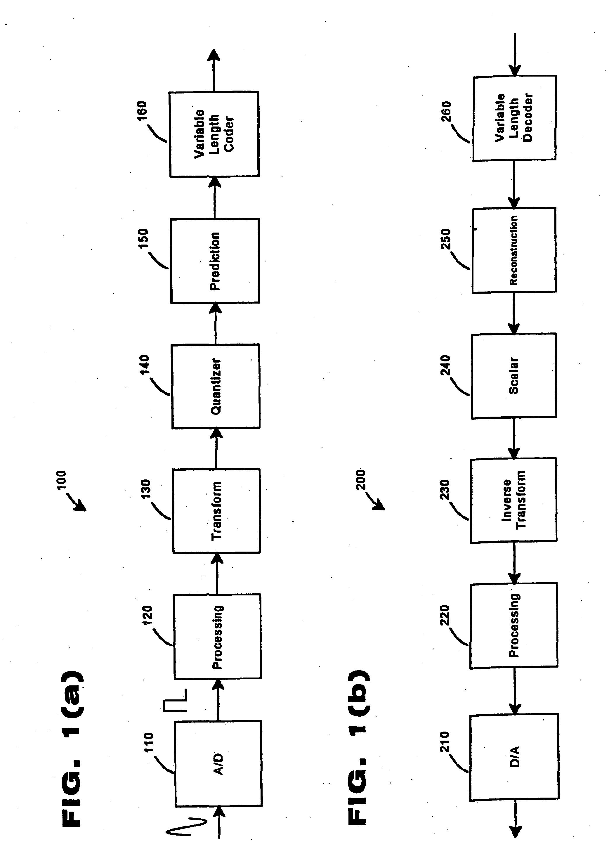
[0012]FIG. 1 shows an encoder 100 constructed in accordance with the present invention. The encoder can include a non-transitory storage medium storing instructions that control a processor to perform steps disclosed herein. An analog image signal is presented to the encoder 100. The image signal is sampled and converted to a digital signal by an analog to digital (“A / D”) converter 110 using techniques known in the art. The A / D converter 110 generates a digital image signal for a plurality of pixels of the image. Alternatively, the image signal may be presented to the encoder as a digital image signal; in this case, the A / D converter 110 is omitted.

[0013]The digital image signal is input to a processing circuit 120. The processing circuit 120 may perform a host of functions. Typically, the processing circuit 120 filters the image data and breaks the image data into a luminance signal component and two chrominance signal components. Additionally, the processing circuit 120 groups ima...

second embodiment

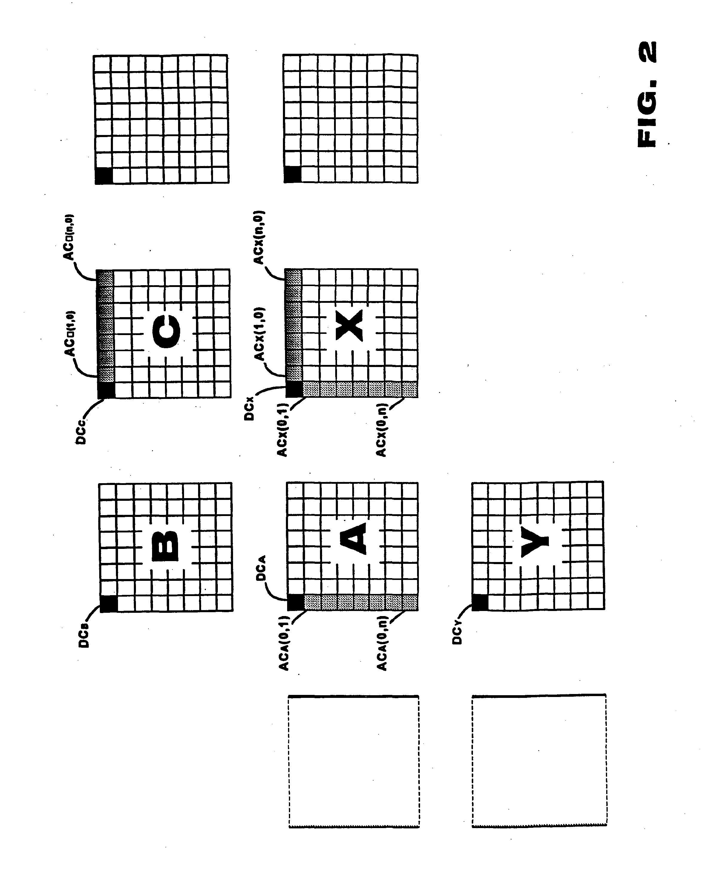
[0047]The prediction and reconstruction process described herein is termed an “implicit” method because no overhead signals are required to identify which of the blocks are used for prediction. In operation, coefficient values of blocks A, B and C are known at both the encoder 100 and the decoder 200. Thus, the decoder 200 can reconstruct the prediction operation of the encoder 100 without additional signaling. In an embodiment where the prediction circuit did not select between modes of AC prediction, the AC prediction and reconstruction is purely implicit. With the addition of an AC prediction flag in a second embodiment, the prediction process is no longer purely implicit.

[0048]The encoding / decoding operation of the prediction and reconstruction circuit may also be performed by software stored in a non-transitory computer-readable storage medium, the software configured to control a programmed micro processor or digital signal processor to perform steps disclosed herein. The soft...


PUM


Abstract

A predictive video coder performs gradient prediction based on previous blocks of image data. For a new block of image data, the prediction determines a horizontal gradient and a vertical gradient from a block diagonally above the new block (vertically above a previous horizontally adjacent block). Based on these gradients, the encoder predicts image information based on image information of either the horizontally adjacent block or a block vertically adjacent to the new block. The encoder determines a residual that is transmitted in an output bitstream. The decoder performs the identical gradient prediction and predicts image information without need for overhead information. The decoder computes the actual information based on the predicted information and the residual from the bitstream.

Description

RELATED APPLICATIONS[0001]This application is a continuation of U.S. patent application Ser. No. 11 / 216,195, filed Aug. 31, 2005, which is a continuation of U.S. patent application Ser. No. 10 / 331,344, filed Dec. 31, 2002 and issued as U.S. Pat. No. 7,092,445 on Aug. 15, 2006, which is a continuation of U.S. patent application Ser. No. 09 / 942,734, filed Aug. 31, 2001 and issued as U.S. Pat. No. 6,556,625 on Apr. 29, 2003, which is a continuation of U.S. patent application Ser. No. 09 / 908,044, filed Aug. 11, 1997 and issued as U.S. Pat. No. 6,341,144 on Jan. 22, 2002, which claims the benefit of priority afforded by provisional application No. 60 / 026,963, filed Sep. 20, 1996, and provisional application No. 60 / 038,019 filed Feb. 14, 1997, the disclosures of which are incorporated herein by reference in their entirety.BACKGROUND OF THE INVENTION[0002]A variety of protocols for communication, storage and retrieval of video images are known. Invariably, the protocols are developed with ...

Claims


Application Information

Patent Timeline
Patent Type & Authority Applications(United States)
IPC IPC(8): H04N7/26
CPCH04N19/00569H04N19/619H04N19/50H04N19/176H04N19/13H04N19/122H04N19/625H04N19/593H04N19/11H04N19/124H04N19/14H04N19/44H04N19/20H04N19/60H04N19/139H04N19/513H04N19/89
Inventor HASKELL, BARIN GEOFFRYPURI, ATULSCHMIDT, ROBERT LEWIS
Owner AT&T INTPROP I L P
Learn More