
Ultrasonic diagnostic apparatus and ultrasonic diagnostic method

a diagnostic apparatus and ultrasonic technology, applied in diagnostics, medical science, instruments, etc., can solve the problems of difficult to obtain quantitative and reproducible values, adverse effects of push pulse on the human body, and ineffective use of b/a coefficients, etc., to achieve effective utilization

Inactive Publication Date: 2011-03-31
FUJIFILM CORP
View PDF5 Cites 20 Cited by
  • Summary
  • Abstract
  • Description
  • Claims
  • Application Information

AI Technical Summary

Benefits of technology

The present invention provides an ultrasonic diagnostic apparatus and method that effectively utilizes the B / A coefficient for diagnosis of a lesion. The inventors focused on the temperature dependence of the B / A coefficient and found that it increases with temperature. The apparatus includes an ultrasonic transducer, harmonic image processor, and acquisition section to acquire information on changes in the B / A coefficient relative to temperature changes. The apparatus can also include a display controller to display the ultrasonic image based on the B / A coefficient. The method involves transmitting ultrasonic waves to an object of interest, receiving echo waves, and calculating the B / A coefficient based on a signal component corresponding to a harmonic component. The obtained B / A coefficient is effectively utilized for diagnosis of a lesion.

Problems solved by technology

Accordingly, it is difficult to obtain quantitative and reproducible values.
It has been pointed out that the push pulse has adverse effects of to the human body.
At present, the B / A coefficient is not effectively used for the diagnosis of a lesion because measurement of an absolute value of the B / A coefficient still has uncertain factors.

Method used


Image

  • Ultrasonic diagnostic apparatus and ultrasonic diagnostic method
  • Ultrasonic diagnostic apparatus and ultrasonic diagnostic method
  • Ultrasonic diagnostic apparatus and ultrasonic diagnostic method

Examples


Embodiment Construction

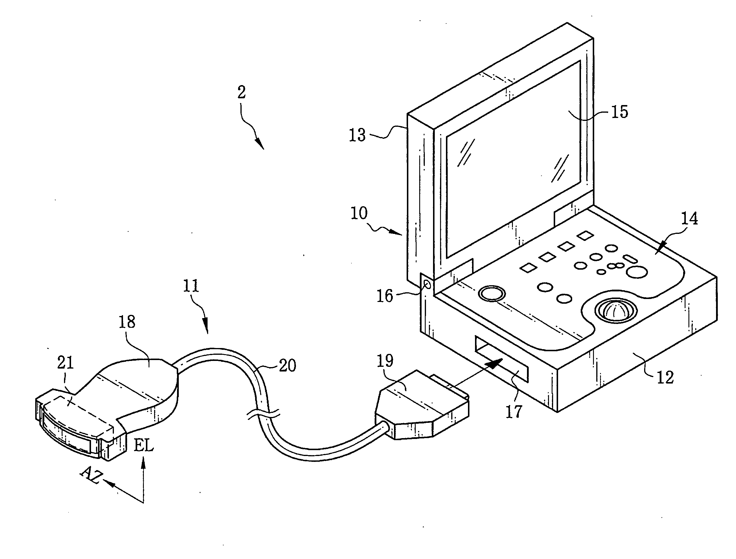
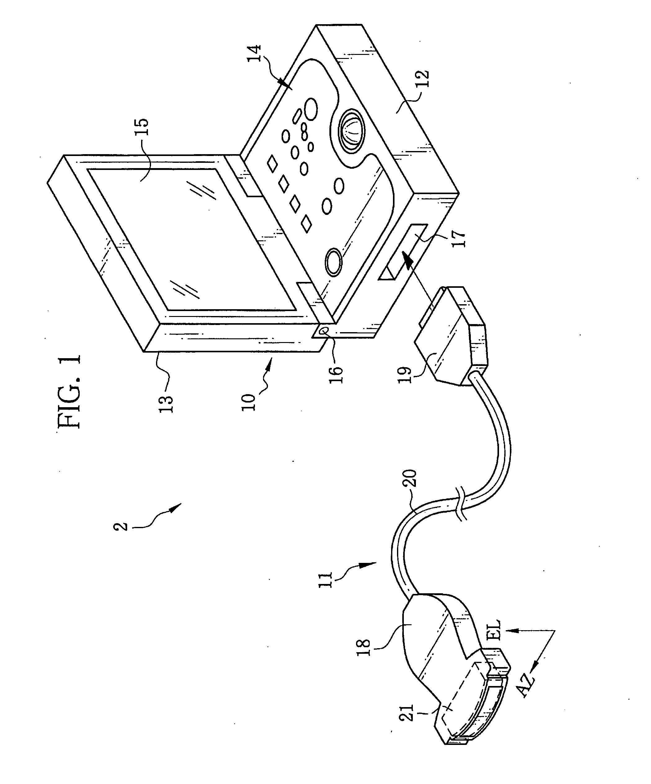
[0031]In FIG. 1, an ultrasonic diagnostic apparatus 2 is composed of a portable ultrasonic observation device 10 or imaging device and an external ultrasonic probe 11. The portable ultrasonic observation device 10 is composed of a housing 12 and a cover 13. An operation section 14 is provided on the top surface of the housing 12. The operation section 14 has buttons and a trackball to input various operation instructions to the portable ultrasonic observation device 10. On an inner surface of the cover 13, a monitor 15 is provided. The monitor 15 displays various operation screens including an ultrasonic image.

[0032]The cover 13 is attached to the housing 12 through a hinge 16. The cover 13 is rotatable between an open position and a closed position. In the open position, the operation section 14 and the monitor 15 are exposed. In the closed position, the inner surface and the top surface of the housing 12 face each other to cover the operation section 14 and the monitor 15 with eac...


PUM


Abstract

An ultrasonic probe has a plurality of ultrasonic transducers (UTs). Each UT transmits ultrasonic waves and receives echo waves. In a B / A coefficient acquisition mode, every time a transmission of the ultrasonic waves and reception of echo waves takes place, ultrasonic waves for heating are transmitted to heat an object of interest. An HI processor calculates a non-linear B / A coefficient based on a harmonic component of a detection signal from the UT. The HI processor acquires information of changes in the B / A coefficient while the object of interest is heated with the ultrasonic waves for heating. A DSC displays the information of the B / A coefficient together with an ultrasonic image on a monitor.

Description

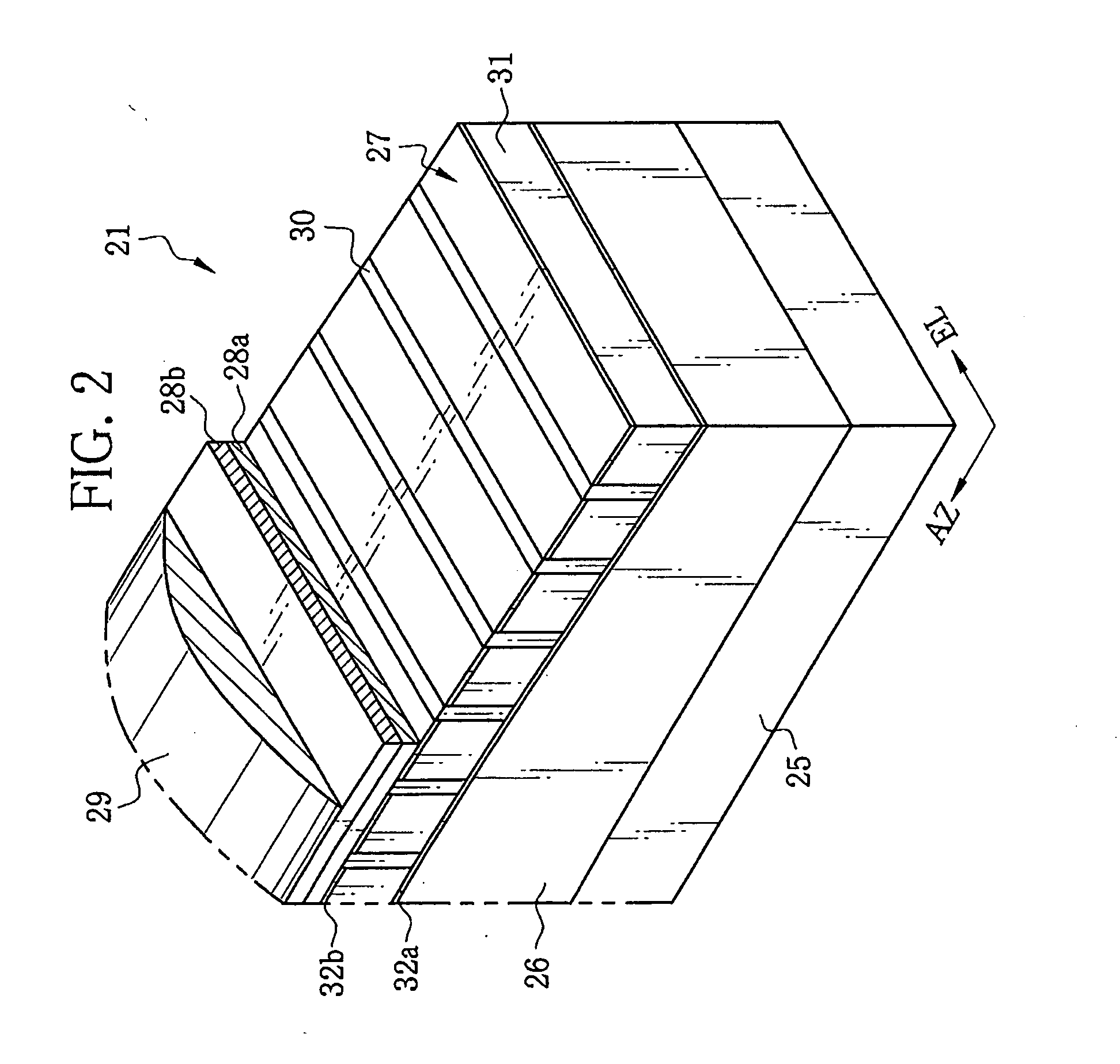
FIELD OF THE INVENTION[0001]The present invention relates to an ultrasonic diagnostic apparatus and an ultrasonic diagnostic method for performing diagnosis of a lesion based on a B / A coefficient obtained from a harmonic component of echo waves.BACKGROUND OF THE INVENTION[0002]Medical diagnosis using an ultrasonic diagnostic apparatus is commonly performed. The ultrasonic diagnostic apparatus is composed of an ultrasonic probe and an ultrasonic observation device. At a tip of the ultrasonic probe, a plurality of ultrasonic transducers (hereinafter abbreviated as UTs) are arranged. Each UT is composed of a backing material, a piezoelectric element, a pair of electrodes, an acoustic matching layer, and an acoustic lens. The UTs transmit ultrasonic waves to a subject (human body) and receive echo waves therefrom. Thereby detection signals are outputted from the UTs. The detection signals are electrically processed in an ultrasonic observation device or imaging device. Thus, an ultrason...

Claims


Application Information

Patent Timeline
Patent Type & Authority Applications(United States)
IPC IPC(8): A61B8/00
CPCA61B5/01A61B8/00A61B8/4472G01S7/52038A61B8/56G01S7/5208G01S7/52082A61B5/7232G01S7/52074A61B8/4427A61B8/4483
Inventor OSAWA, ATSUSHI
Owner FUJIFILM CORP
Learn More