Non-azeotropic refrigerant mixture and refrigeration cycle apparatus
a technology of non-azeotropic refrigerant and mixture, which is applied in the direction of refrigerating machines, lighting and heating apparatus, chemistry apparatus and processes, etc., can solve the problems of smaller global warming potential and lower chemical stability of hydrofluoroolefin, and achieve high reliability of operation and high reliability of operation.
- Summary
- Abstract
- Description
- Claims
- Application Information
AI Technical Summary
Benefits of technology
Problems solved by technology
Method used
Image
Examples
embodiment 1
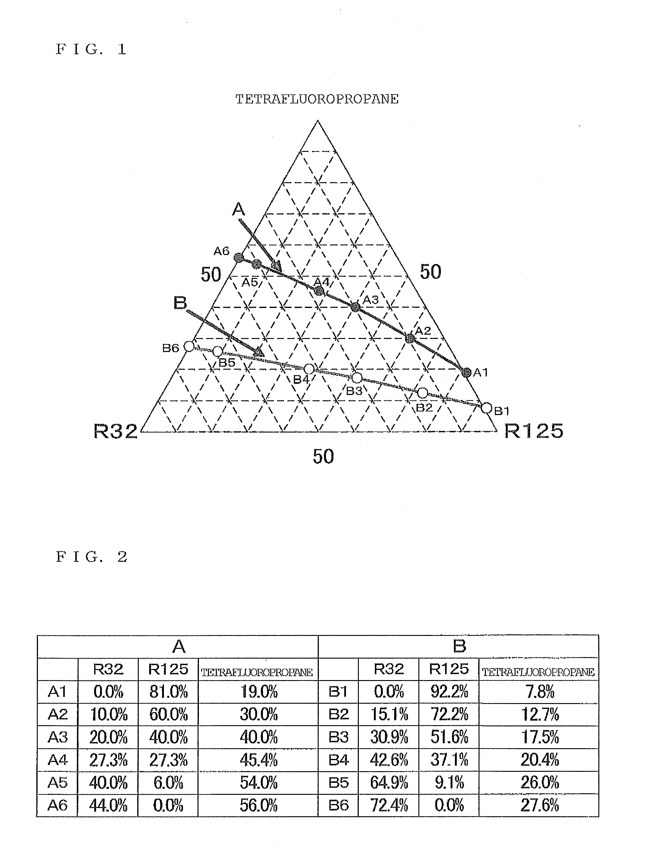
[0029]FIG. 1 is a triangular coordinate representing an equilibrium state of a non-azeotropic refrigerant mixture as a working fluid for a refrigeration cycle apparatus at a constant temperature and under a constant pressure. FIG. 2 is a table illustrating a mixing ratio of the working fluid in FIG. 1. With reference to FIGS. 1 and 2, an equilibrium state of a working fluid at a constant temperature and under a constant pressure will be described. The working fluid consists of a mixture of three chlorofluorocarbons, namely, difluoromethane (R32) and pentafluoroethane (R125) as low-boiling refrigerants, and tetrafluoropropane, which is one of hydrofluoroolefins, as a high-boiling refrigerant.
[0030]In FIG. 1, each single substance, i.e., tetrafluoropropane, R32 or R125 is disposed at each vertex of the triangle. Tetrafluoropropane, R32 and R125 are disposed in this order from the top vertex in a counterclockwise direction. In particular, tetrafluoropropane is disposed at the top verte...
embodiment 2
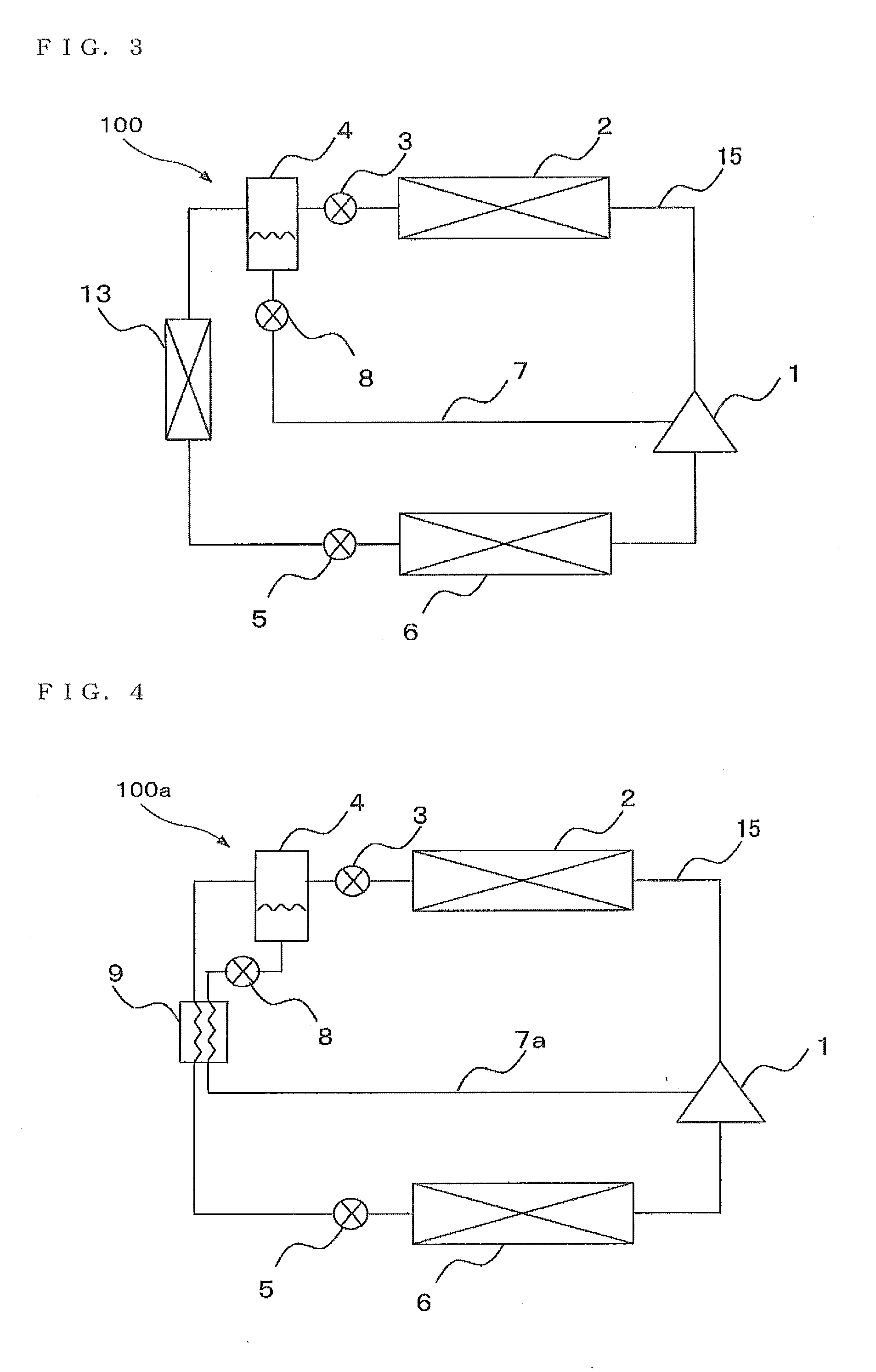
[0035]FIG. 3 schematically illustrates a refrigerant circuit configuration of a refrigeration cycle apparatus 100 according to Embodiment 2 of the invention. With reference to FIG. 3, a configuration and an operation of the refrigeration cycle apparatus 100 will be described. The refrigeration cycle apparatus 100, operating as a cooling apparatus or a heating apparatus, incorporates a refrigeration cycle through which a non-azeotropic refrigerant mixture circulates as a working fluid. The non-azeotropic refrigerant mixture includes a high-boiling refrigerant (namely tetrafluoropropane) and a low-boiling refrigerant (e.g., R32 or R125, or R32 or R125) mixed together. Illustrations of the components in FIG. 3 and the following drawings are not always to scale.
[0036]As illustrated in FIG. 3, the refrigeration cycle apparatus 100 includes a compressor 1, a condenser 2, a first decompressor 3, a vapor / liquid separator 4, an auxiliary condenser 13, a second decompressor 5 and an evaporato...
embodiment 3
[0045]FIG. 4 schematically illustrates a refrigerant circuit configuration of a refrigeration cycle apparatus 100a according to Embodiment 3 of the invention. With reference to FIG. 4, a configuration and an operation of the refrigeration cycle apparatus 100a will be described. The refrigeration cycle apparatus 100a performs cooling operation or heating operation using a refrigeration cycle through which a non-azeotropic refrigerant mixture circulates as a working fluid. The non-azeotropic refrigerant mixture includes a high-boiling refrigerant (namely tetrafluoropropane) and a low-boiling refrigerant (e.g., R32 or R125, or R32 or R125) mixed together. In Embodiment 3, the same components as those of Embodiment 2 are denoted by the same reference numerals. Differences from Embodiment 2 will be described mainly.
[0046]The refrigeration cycle apparatus 100a has a configuration substantially similar to that of the refrigeration cycle apparatus 100 according to Embodiment 2 except that t...
PUM
| Property | Measurement | Unit |
|---|---|---|
| pressure | aaaaa | aaaaa |
| temperatures | aaaaa | aaaaa |
| temperatures | aaaaa | aaaaa |
Abstract
Description
Claims
Application Information
 - R&D
- Intellectual Property
- Life Sciences
- Materials
- Tech Scout
- Unparalleled Data Quality
- Higher Quality Content
- 60% Fewer Hallucinations
Browse by: Latest US Patents, China's latest patents, Technical Efficacy Thesaurus, Application Domain, Technology Topic, Popular Technical Reports.
© 2025 PatSnap. All rights reserved.Legal|Privacy policy|Modern Slavery Act Transparency Statement|Sitemap|About US| Contact US: help@patsnap.com


