Image processing apparatus, method, and recording medium

a technology of image processing and recording medium, applied in the field of image processing apparatus, a method, and a recording medium, can solve the problems of high computation load, and achieve the effect of reducing color unevenness

Inactive Publication Date: 2011-04-07
FUJIFILM CORP
View PDF4 Cites 11 Cited by
  • Summary
  • Abstract
  • Description
  • Claims
  • Application Information

AI Technical Summary

Benefits of technology

[0032]According to the presently disclosed subject matter, it is possible to reduce unevenness in color in a final intermediate-viewpoint image caused by pixels being present only in one of intermediate-viewpoint images.

Problems solved by technology

The art described in Japanese Patent Application Laid-Open No. 2006-65862, however, is disadvantageous in that it requires two mapping computations for obtaining one intermediate-viewpoint image, involving high computation load.

Method used


Image

  • Image processing apparatus, method, and recording medium
  • Image processing apparatus, method, and recording medium
  • Image processing apparatus, method, and recording medium

Examples


first embodiment

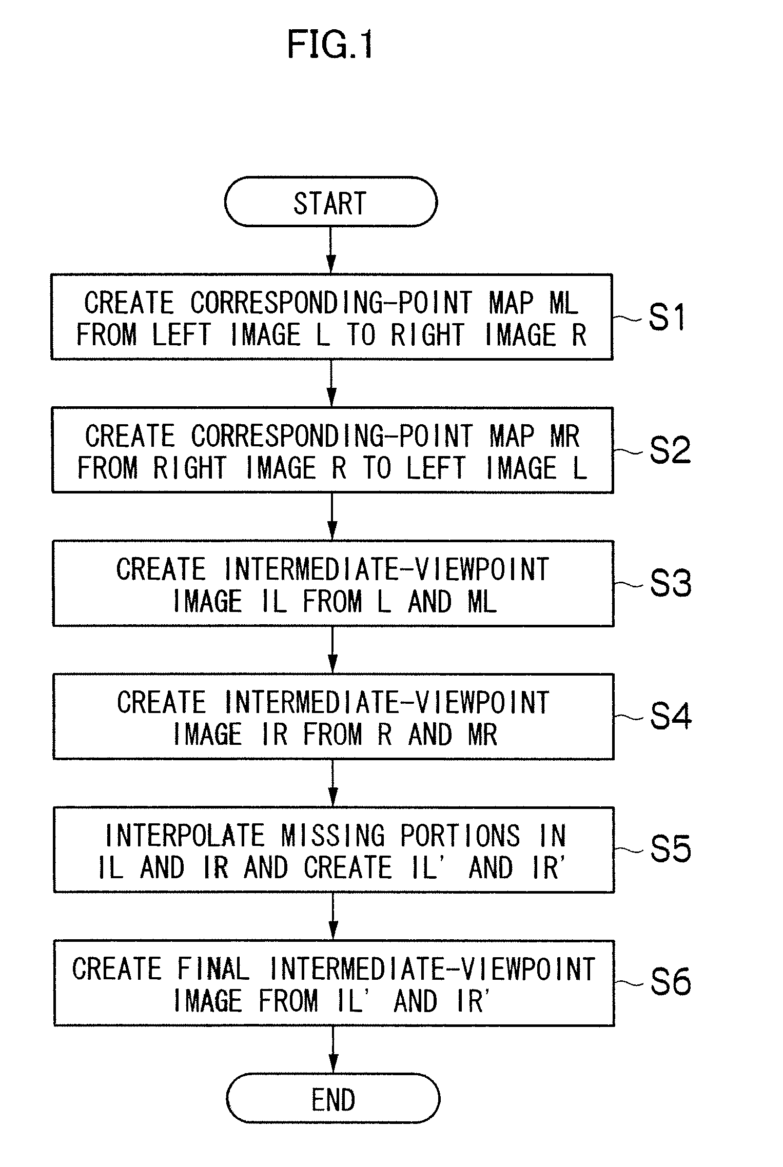
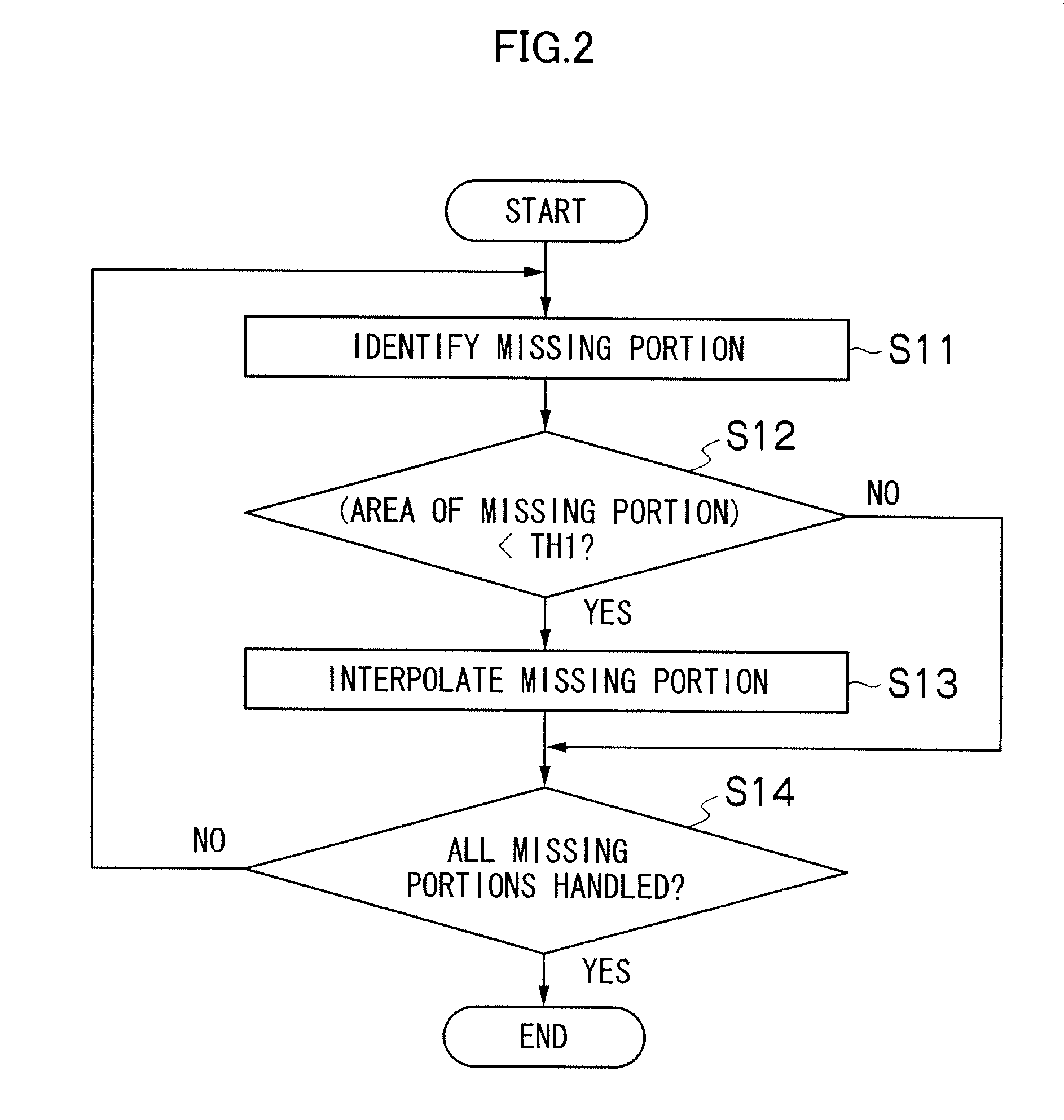
[0049]FIG. 2 is a flowchart illustrating a process of interpolating missing portions according to a first embodiment.

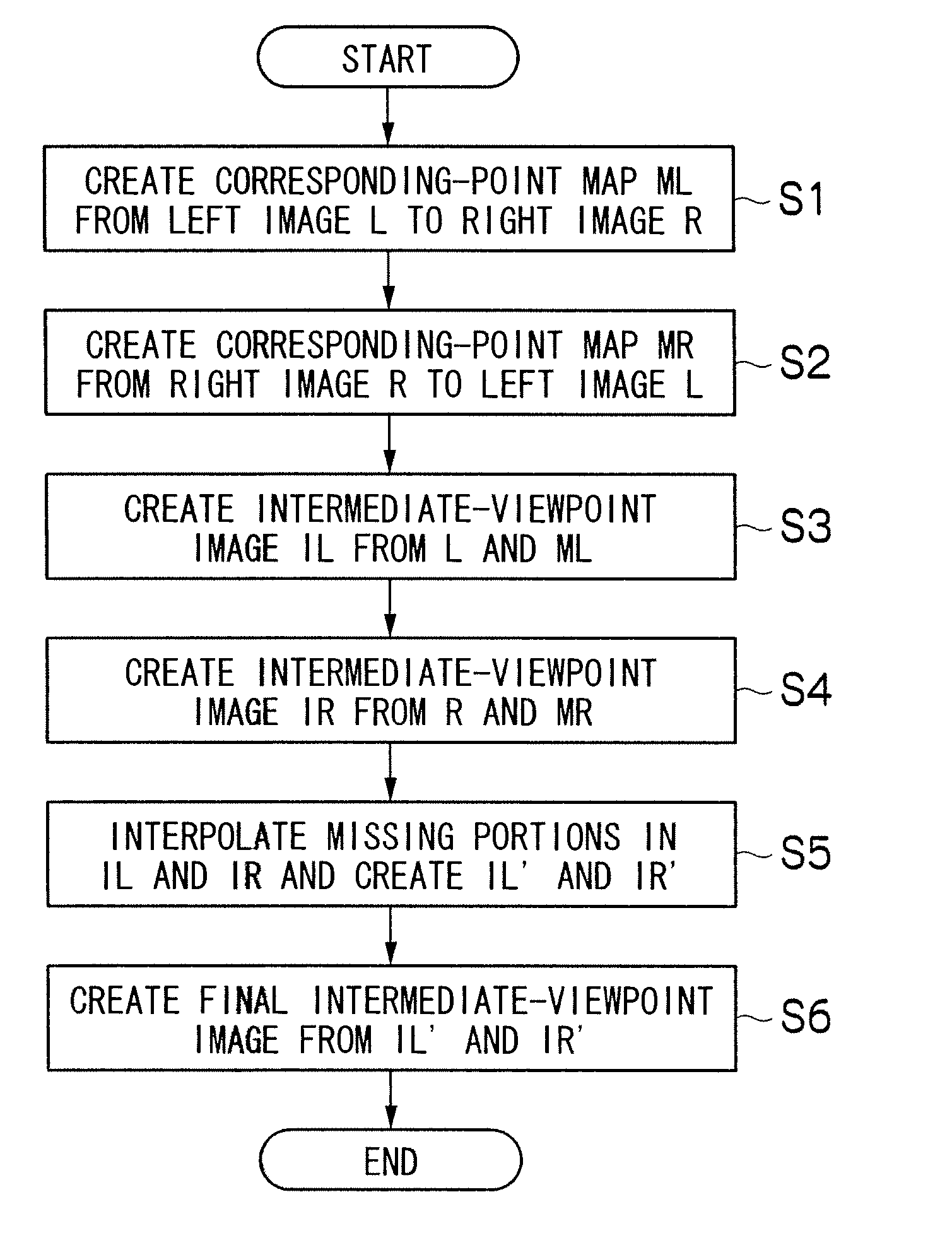
[0050]First, a missing portion is identified in the intermediate-viewpoint image IL which is based on the left image L (step S11). A missing portion refers to a portion or region in which a pixel corresponding to a reference image is not laid within an intermediate-viewpoint image due to difference in the amount of movement between neighboring pixels during forward mapping for creating an intermediate-viewpoint image, like region Z illustrated in FIG. 9.

[0051]Then, the area of the missing portion identified is calculated, and it is determined whether the area is smaller than a threshold TH1 or not (step S12). Although the region Z in FIG. 9 is illustrated as being only one pixel in size in the vertical direction of the intermediate-viewpoint image IL, an actual missing portion can be present spreading in the vertical direction. In this way, the area of a missing porti...

second embodiment

[0060]FIG. 3 is a flowchart illustrating a process of interpolating missing portions according to a second embodiment. Steps common to the flowchart of FIG. 2 are given the same reference numerals and their detailed descriptions are omitted.

[0061]As in the first embodiment, a missing portion is identified in the intermediate-viewpoint image IL which is based on the left image L (step S11).

[0062]Then, a region corresponding to the missing portion identified at step S11 (i.e., a region at the same coordinate position as the missing portion) is extracted from the intermediate-viewpoint image IR which is based on the right image R, and a pixel variance value is calculated from the pixel values (luminance values) of pixels in the region (step S21). The pixel variance value may also be derived from the right image R, in which case a region in the right image R corresponding to the missing portion is identified and extracted through coordinate transformation.

[0063]Determination is made as ...

third embodiment

[0080]FIG. 6 is a flowchart illustrating a process of interpolating a missing portion according to a third embodiment. According to the third embodiment, the area and a variance value of a missing portion are determined before interpolation of the missing portion.

[0081]As in the previous embodiments, a missing portion is identified in the intermediate-viewpoint image IL which is based on the left image L (step S11).

[0082]Then, the area of the missing portion is calculated and it is determined whether the area is smaller than the threshold value TH1 (step S12).

[0083]If the area of the missing portion is equal to or larger than the threshold value TH1, it is determined that an error associated with interpolation is likely to occur, and the flow proceeds to step S14 without performing interpolation.

[0084]If the area of the missing portion is smaller than the threshold value TH1, a region corresponding to the missing portion identified at step S11 is extracted from the intermediate-view...


PUM


Abstract

An image processing method executed in an apparatus, includes steps of: inputting a left-viewpoint image and a right-viewpoint image therebetween to the apparatus; searching for a corresponding point in the right-viewpoint image with respect to the left-viewpoint image, generating a first corresponding-point map based on a result of the searching, and generating a first intermediate-viewpoint image based on the left-viewpoint image; searching for a corresponding point in the left-viewpoint image with respect to the right-viewpoint image, generating a second corresponding-point map based on a result of the searching, and generating a second intermediate-viewpoint image based on the right-viewpoint image; extracting missing portions of pixels in the first and second intermediate-viewpoint images; determining whether a missing portion extracted is a missing portion to be interpolated or not; interpolating the missing portion to be interpolated based on a result of determination; and generating a third intermediate-viewpoint image based on the intermediate-viewpoint images.

Description

BACKGROUND OF THE INVENTION[0001]1. Field of the Invention[0002]The presently disclosed subject matter relates to an image processing apparatus, a method, and a recording medium. More particularly, the presently disclosed subject matter relates to an image processing apparatus, a method, and a recording medium which are configured to reduce unevenness in color in a final intermediate-viewpoint image caused by pixels being present only in one of a plurality of intermediate-viewpoint images.[0003]2. Description of the Related Art[0004]A technique to generate an image corresponding to an arbitrary intermediate viewpoint from two images with different viewpoints that are taken as a stereo image is important for preparing a stereoscopic photoprint with a lenticular lens sheet attached on a surface thereof or displaying an appropriate stereo image on various types of a stereo image display device.[0005]To generate images corresponding to an intermediate viewpoint (intermediate-viewpoint i...

Claims


Application Information

Patent Timeline
Patent Type & Authority Applications(United States)
IPC IPC(8): H04N13/00
CPCG06T7/0022G06T2207/20228G06T2207/10012G06T7/97
Inventor ENDO, HISASHIKOKUBUN, HIDEAKI
Owner FUJIFILM CORP
Why Eureka
Try Eureka