Signal conversion circuit, and multiple primary color liquid crystal display device having the circuit

Inactive Publication Date: 2011-04-07
SHARP KK
View PDF23 Cites 56 Cited by
  • Summary
  • Abstract
  • Description
  • Claims
  • Application Information

AI Technical Summary

Benefits of technology

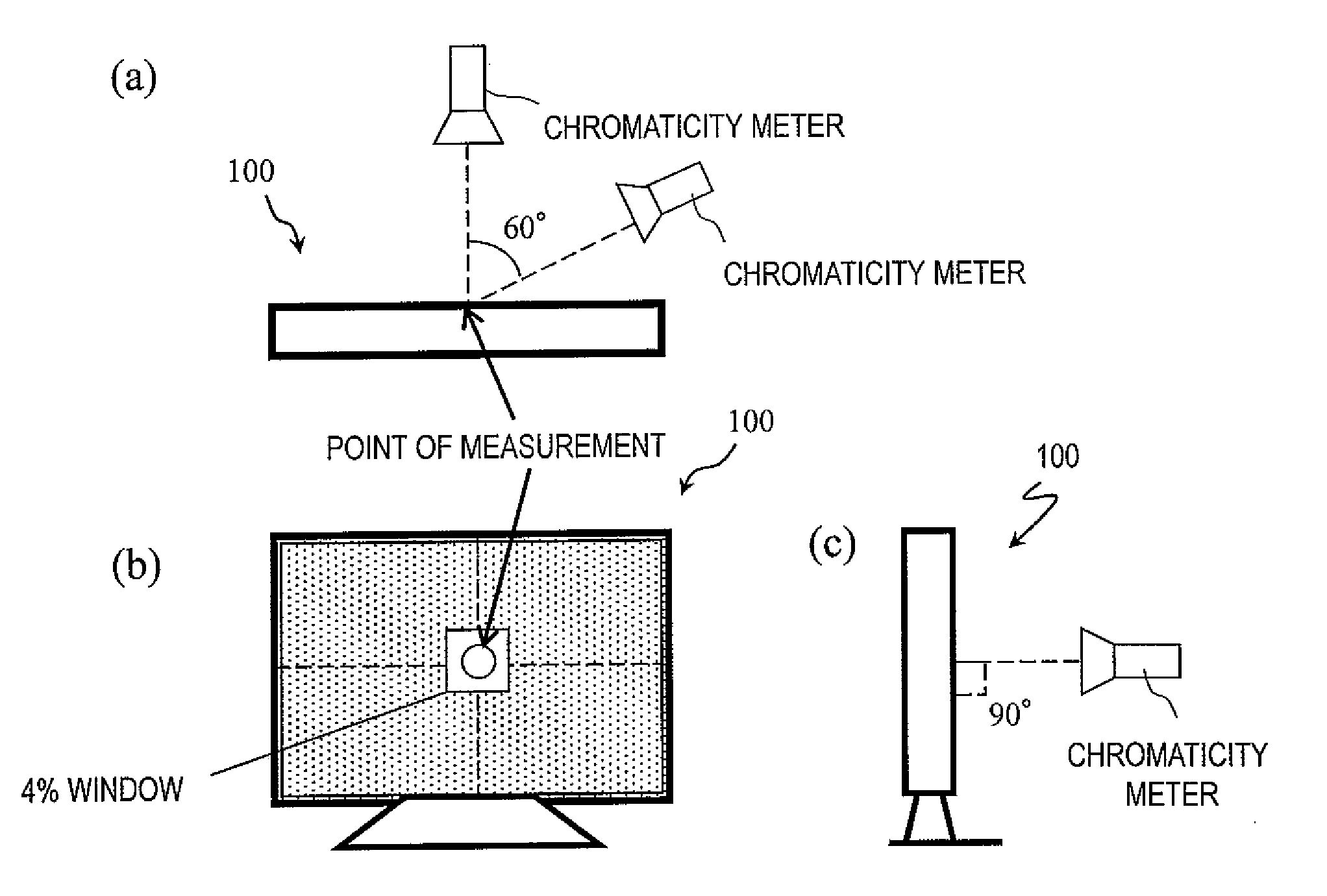
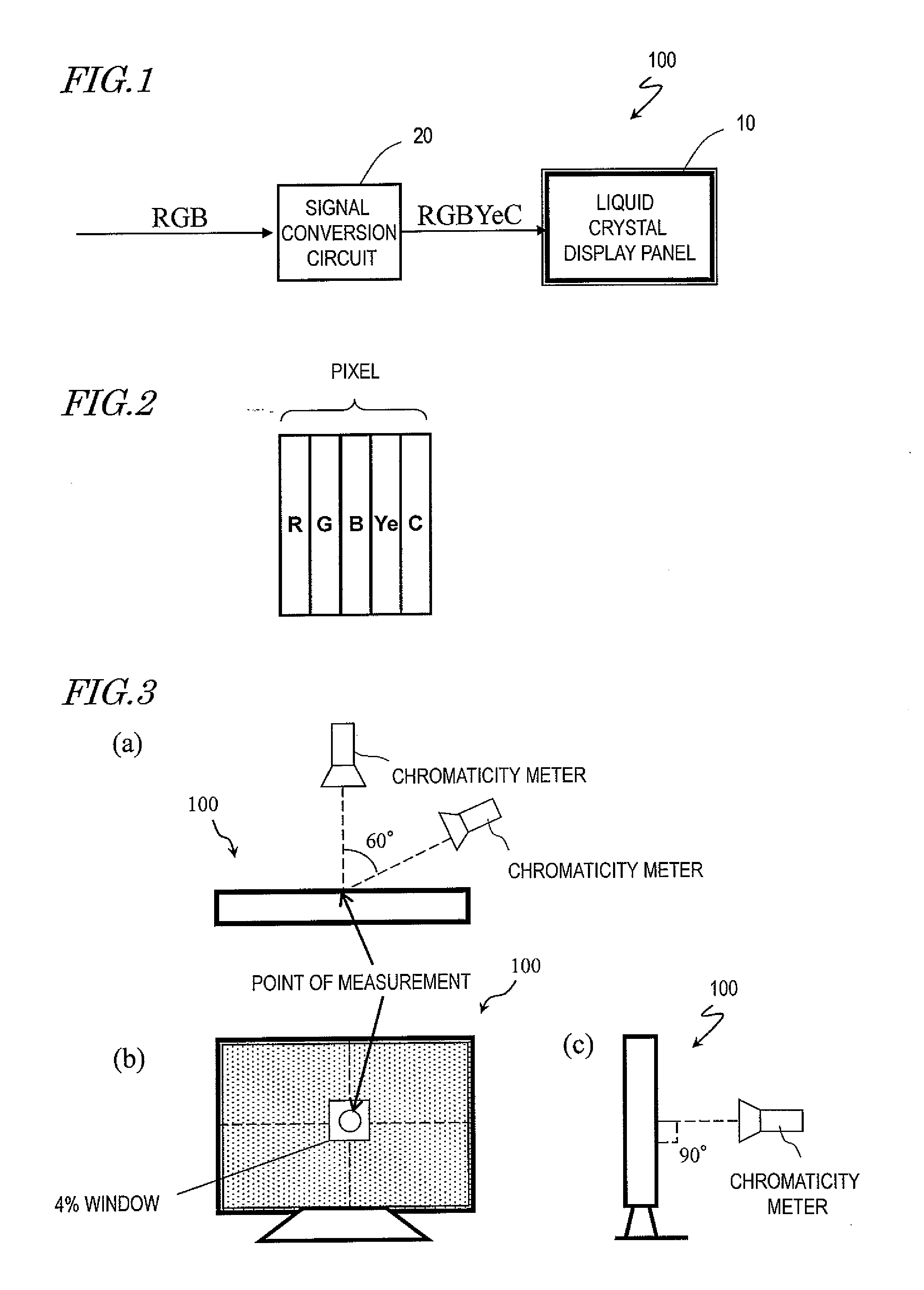
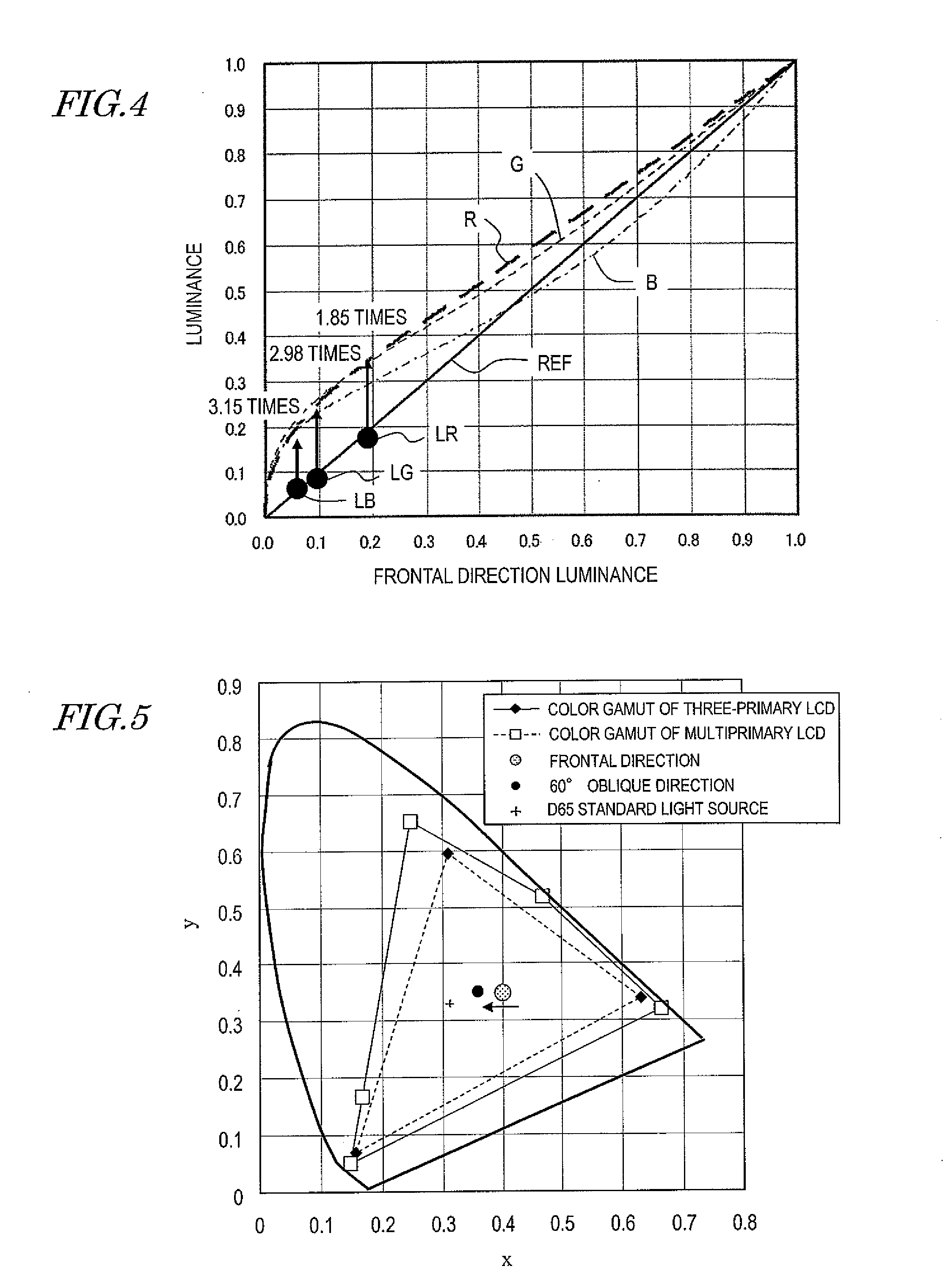
[0026]When converting an input video signal to a multiprimary signal corresponding to four or more primary colors, the signal conversion circuit according to the present invention applies a conversion to the video signal so that a difference between a chromaticity when a pixel is viewed from the front and a chromaticity when the pixel is viewed from an oblique direction is smaller than a predetermined value.
[0027]Specifically, when generating a multiprimary signal for displaying dark skin, the signal conversion circuit according to the present invention applies a conversion to a video signal so that a color difference Δu′v′=((u′−u60′)2+(v′−v60′)2) is 0.03 or less, the color difference Δu′v′ being defined by CIE1976 chromaticity coor

Problems solved by technology

However, conventional display devices have a problem in that they can only display colors in a narrow range (referred to as a “color gamut”). FIG. 21 shows a color gamut of a conventional display device which performs display by using three primaries. FIG. 21 is an xy chromaticit

Method used


Image

  • Signal conversion circuit, and multiple primary color liquid crystal display device having the circuit
  • Signal conversion circuit, and multiple primary color liquid crystal display device having the circuit
  • Signal conversion circuit, and multiple primary color liquid crystal display device having the circuit

Examples


Embodiment Construction

[0051]Liquid crystal display devices of the TN (Twisted Nematic) mode and the STN (Super Twisted Nematic) mode, which have conventionally been commonly used, have a disadvantage of a narrow viewing angle, and various display modes have been developed to improve this.

[0052]As display modes having improved viewing angle characteristics, the IPS (In-Plane Switching) mode disclosed in Japanese Examined Patent Publication No. 63-21907, the MVA (Multi-domain Vertical Alignment) mode disclosed in Japanese Laid-Open Patent Publication No. 11-242225, the CPA (Continuous Pinwheel Alignment) mode disclosed in Japanese Laid-Open Patent Publication No. 2003-43525, and the like are known.

[0053]In the aforementioned display modes, high-quality displaying is realized with a wide viewing angle. However, in vertical alignment modes (VA modes) with a wide viewing angle, e.g., the MVA mode or the CPA mode, as a problem regarding viewing angle characteristics, a problem has newly emerged in that there i...


PUM


Abstract

There is provided a signal conversion circuit which is suitably used in a multiprimary liquid crystal display device (especially a multiprimary liquid crystal display device which performs display in a vertical alignment mode), and a multiprimary liquid crystal display device having such a signal conversion circuit.
A signal conversion circuit according to the present invention is for use in a multiprimary liquid crystal display device which performs display in a vertical alignment mode, and converts an input video signal to a multiprimary signal corresponding to four or more primary colors. When generating a multiprimary signal for displaying dark skin, the signal conversion circuit according to the present invention applies a conversion to the video signal so that a color difference Δu′v′=((u′−u60′)2+(v′−v60′)2) is 0.03 or less, the color difference Δu′v′ being defined by CIE1976 chromaticity coordinates (u′, v′) representing a chromaticity when the pixel is viewed from the frontal direction and CIE1976 chromaticity coordinates (u60′, v60′) representing a chromaticity when the pixel is viewed from a 60° oblique direction.

Description

TECHNICAL FIELD[0001]The present invention relates to a liquid crystal display device, and more particularly to a multiprimary liquid crystal display device which performs display by using four or more primary colors. The present invention also relates to a signal conversion circuit for use in such a liquid crystal display device.BACKGROUND ART[0002]Currently, various display devices are used in a variety of applications, including liquid crystal display devices. In commonly-used display devices, each pixel is composed of three subpixels for displaying three primaries of light, i.e., red, green and blue, whereby multicolor display is achieved.[0003]However, conventional display devices have a problem in that they can only display colors in a narrow range (referred to as a “color gamut”). FIG. 21 shows a color gamut of a conventional display device which performs display by using three primaries. FIG. 21 is an xy chromaticity diagram in an XYZ color system, where a color gamut is sho...

Claims


Application Information

Patent Timeline
IPC IPC(8): H04N9/30H04N7/01
CPCG02F1/133707G09G2340/06G02F2201/52G09G3/006G09G3/2003G09G3/3607G09G3/3611G09G5/02G09G2300/0426G09G2300/0443G09G2300/0452G09G2300/0486G09G2320/0242G09G2320/028G02F2001/134372G02F1/134372
Inventor TOMIZAWA, KAZUNARINAKAMURA, KOHZOHUEKI, SHUNMORI, TOMOHIKOYOSHIDA, YUICHI
Owner SHARP KK
Why Eureka
Try Eureka