

Pump
a technology for pumping and fluid, applied in the direction of machines/engines, oscillating piston liquid engines, positive displacement liquid engines, etc., can solve the problems of reduced use of the actuator on the fluid, reduced pump efficiency, and reduced pump efficiency, and achieves reduced vibration mode matching of the substantial area fraction of the end walls and working fluid volume, and limited piezoelectric material volume. , the effect of increasing the outer diameter
- Summary
- Abstract
- Description
- Claims
- Application Information
AI Technical Summary
Benefits of technology
Problems solved by technology
Method used
Image

Examples
Embodiment Construction
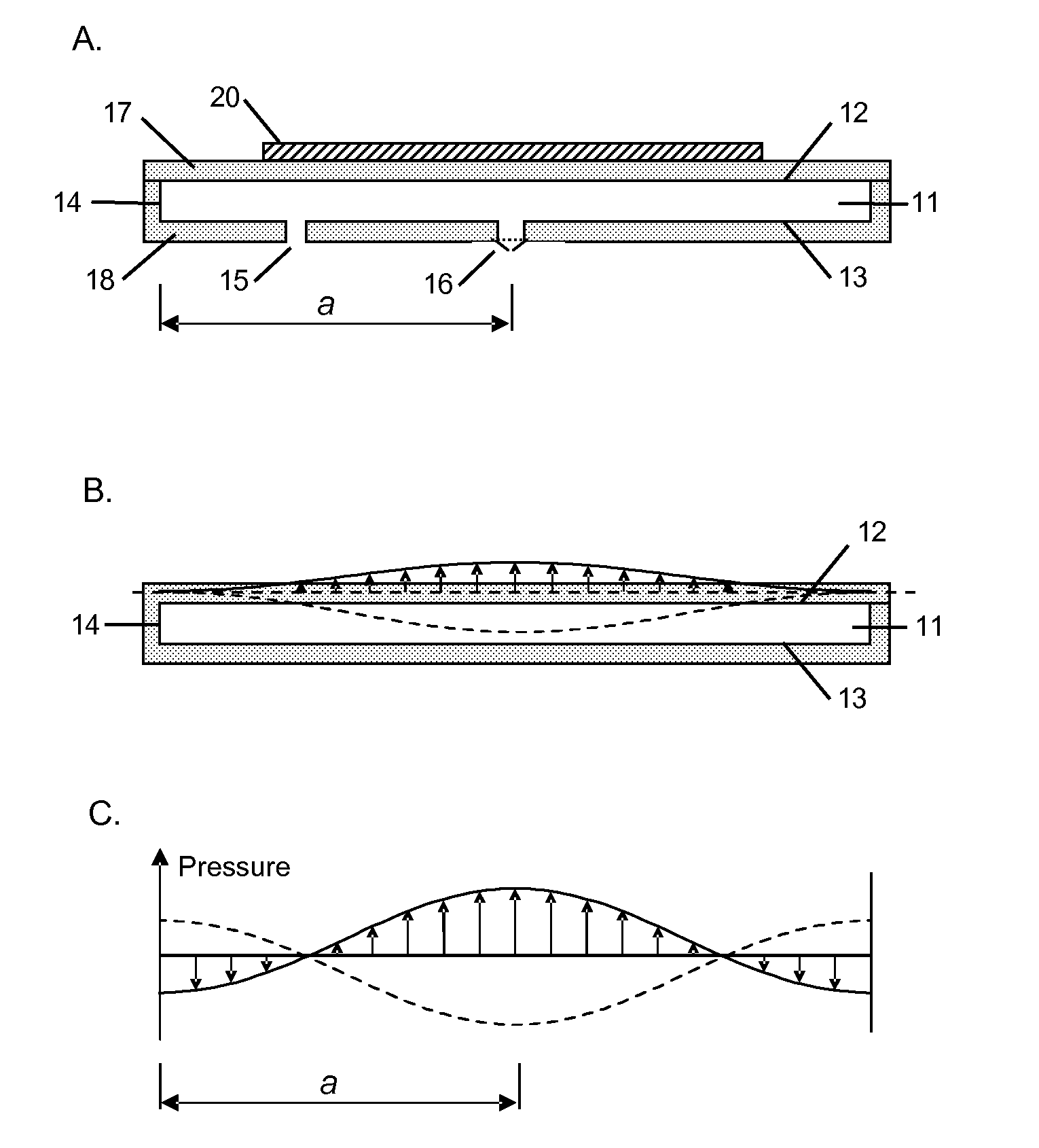
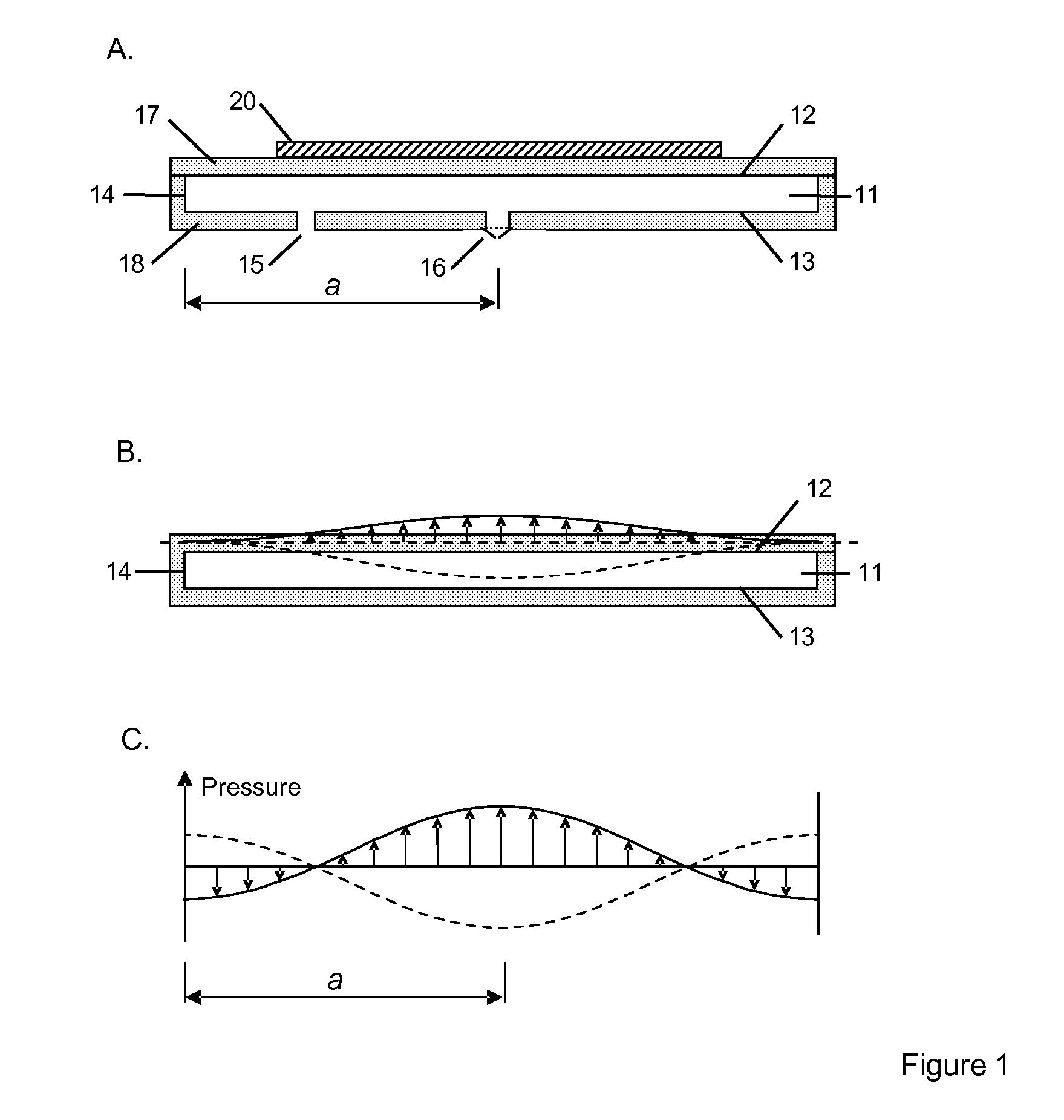
[0051]FIG. 1A is a schematic representation of the pump according to the prior art. A cavity 11 is defined by end walls 12 and 13, and a side wall 14. The cavity is substantially circular in shape, although elliptical and other shapes could be used. The cavity 11 is provided with a nodal air inlet 15, which in this example is unvalved. There is also a valved air outlet 16 located substantially at the centre of end wall 13. The first end-wall 12 is defined by the lower surface of a disc 17 attached to a main body 18. The inlet and outlet pass through the main body 18.
[0052]The actuator comprises a piezoelectric disc 20 attached to a disc 17. When an appropriate electrical drive is applied, the actuator is caused to vibrate in a direction substantially perpendicular to the plane of the cavity, thereby generating radial pressure oscillations within the fluid in the cavity.
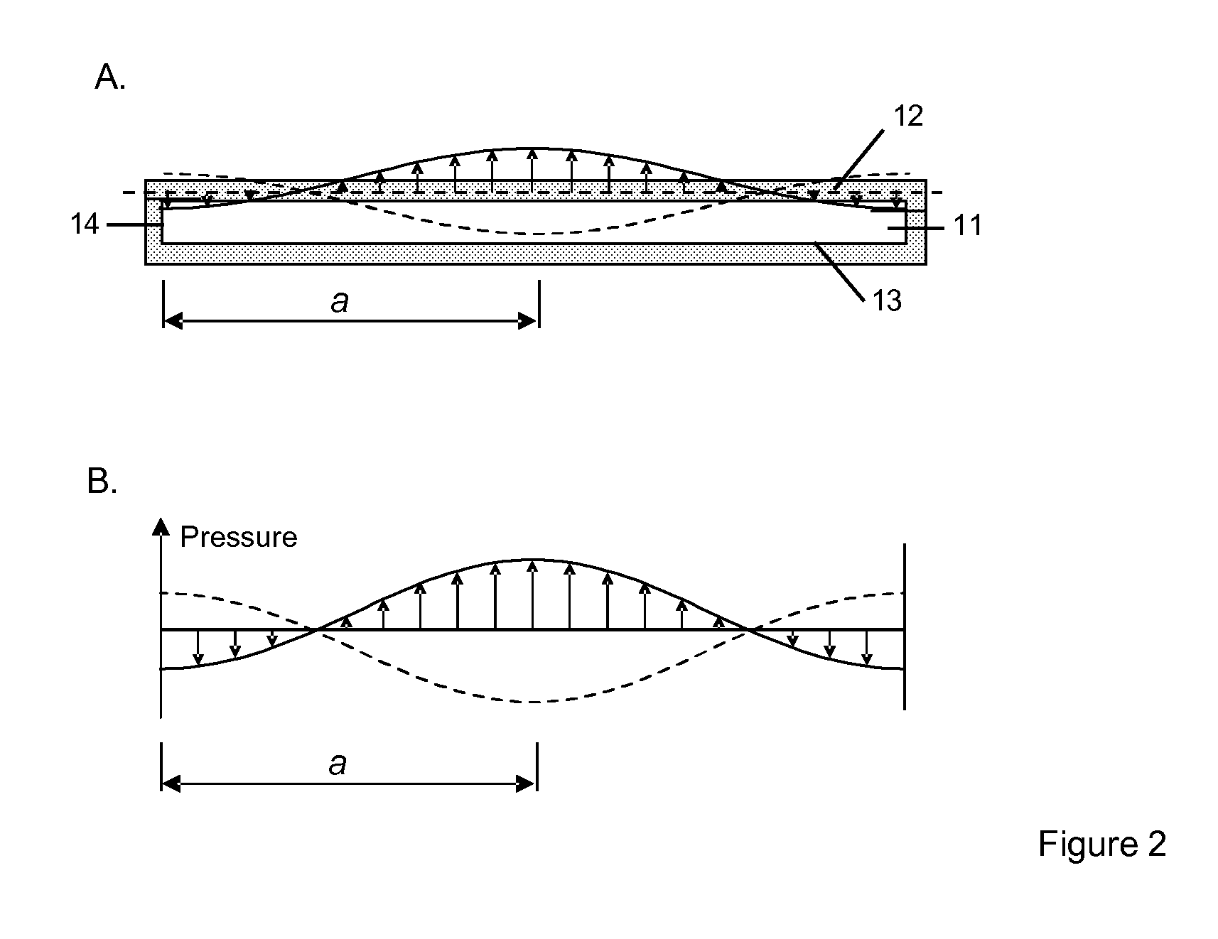
[0053]FIG. 1B shows one possible displacement profile of the driven wall 12 of the cavity. In this case the amplitu...
PUM
 Abstract
Description
Claims
Application Information