Rankine cycle system

a cycle system and cycle technology, applied in steam engine plants, machines/engines, mechanical equipment, etc., can solve the problems of large amounts of waste heat simply dumped into the atmosphere, oxides and particulates may be emitted, and conventional heat recovery systems do not operate with sufficient efficiency to make energy recovery cost-effective,

Inactive Publication Date: 2011-04-14
GENERAL ELECTRIC CO
View PDF10 Cites 66 Cited by
  • Summary
  • Abstract
  • Description
  • Claims
  • Application Information

AI Technical Summary

Problems solved by technology

When waste heat is low grade, such as waste heat having a temperature of heat below 840 degrees Fahrenheit, for example, conventional heat recovery systems do not operate with sufficient efficiency to make recovery of energy cost-effective.
The net result is that vast quantities of waste heat are simply dumped into the atmosphere, ground, or water.
However, atmospheric emissions such as nitrogen oxides and particulates may be emitted.
Hence conventional rankine cycle has constraints that it can operate only at design state points (pressures, mass flows and temperatures).
During partial load conditions or off design operating conditions, the rankine cycle can only be operated at a limited range of state points.
As a result, the cycle efficiency is lowered and component operation limits are exceeded.

Method used


Image

  • Rankine cycle system
  • Rankine cycle system
  • Rankine cycle system

Examples


Embodiment Construction

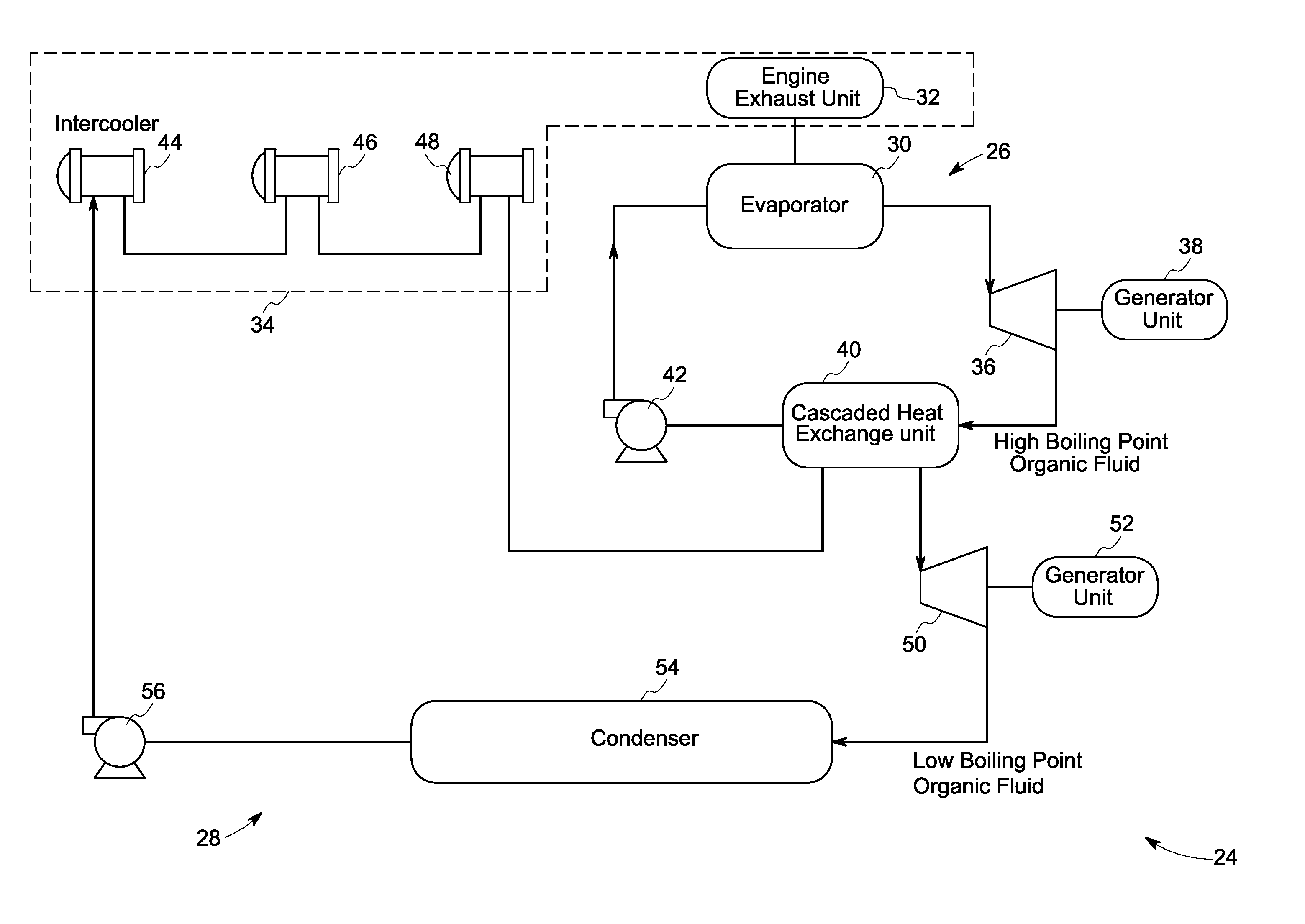
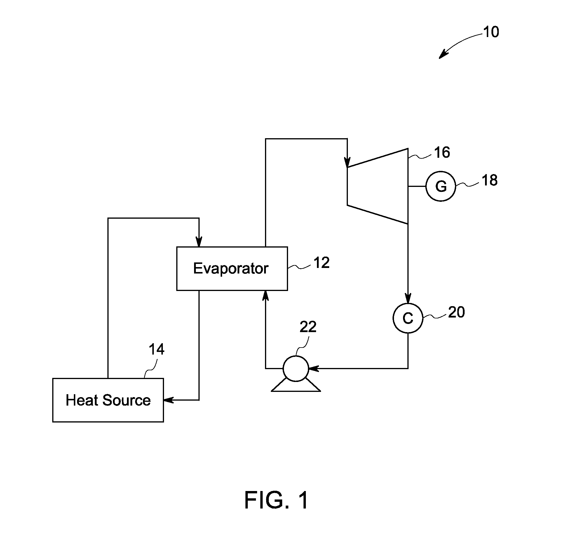
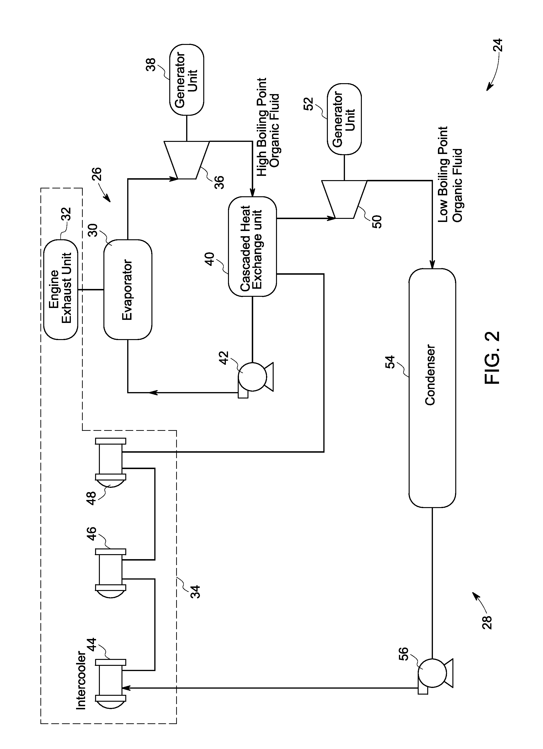
[0014]In accordance with the exemplary embodiments of the present invention, a rankine cycle system is disclosed. The rankine cycle system includes an evaporator coupled to a heat source and configured to circulate a working fluid in heat exchange relationship with a hot fluid from the heat source so as to heat the working fluid and vaporize the working fluid. An expander is coupled to the evaporator and configured to expand the vaporized working fluid from the evaporator. The exemplary expander is operable at variable speed. A condenser is coupled to the expander and configured to condense the vaporized working fluid from the expander. A pump is coupled to the condenser and configured to feed the condensed working fluid from the condenser to the evaporator. In accordance with a specific embodiment of the present invention, a waste heat recovery system including at least two integrated rankine cycle systems having an expander operable at variable speed is disclosed.

[0015]Referring t...


PUM


Abstract

The rankine cycle system includes an evaporator coupled to a heat source and configured to circulate a working fluid in heat exchange relationship with a hot fluid from the heat source so as to heat the working fluid and vaporize the working fluid. An expander is coupled to the evaporator and configured to expand the vaporized working fluid from the evaporator. The exemplary expander is operable at variable speed. A condenser is coupled to the expander and configured to condense the vaporized working fluid from the expander. A pump is coupled to the condenser and configured to feed the condensed working fluid from the condenser to the evaporator.

Description

BACKGROUND[0001]The invention relates generally to rankine cycle system, and more particularly to a rankine cycle system having a variable speed expander.[0002]Enormous amounts of waste heat are generated by a wide variety of industrial and commercial processes and operations. Example sources of waste heat include heat from space heating assemblies, steam boilers, engines, and cooling systems. When waste heat is low grade, such as waste heat having a temperature of heat below 840 degrees Fahrenheit, for example, conventional heat recovery systems do not operate with sufficient efficiency to make recovery of energy cost-effective. The net result is that vast quantities of waste heat are simply dumped into the atmosphere, ground, or water.[0003]Some power generation systems provide better reliability and off-grid operation with alternate fuels such as biogas or landfill gas, with examples being gas turbines and combustion engines such as microturbines and reciprocating engines. Combus...

Claims


Application Information

Patent Timeline
Patent Type & Authority Applications(United States)
IPC IPC(8): F01K25/08
CPCF01K7/025F01K25/08F01K13/02
Inventor AST, GABORFREY, THOMAS JOHANNESHUCK, PIERRE SEBASTIENKOPECEK, HERBERTBARTLETT, MICHAEL ADAM
Owner GENERAL ELECTRIC CO
Why Eureka
Try Eureka