Refrigeration cycle device and method of controlling the same

a technology of refrigerant cycle and cycle device, which is applied in the direction of indirect heat exchanger, subcooler, lighting and heating apparatus, etc., can solve the problems of long time, uncomposed refrigerant, and contributing to the acceleration of global warming, so as to prevent an increase in pressure loss

Active Publication Date: 2011-04-14
MITSUBISHI ELECTRIC CORP
View PDF10 Cites 34 Cited by
  • Summary
  • Abstract
  • Description
  • Claims
  • Application Information

AI Technical Summary

Benefits of technology

[0017]Therefore, the refrigeration cycle device of the present invention allows the refrigerant at the upstream side of the expansion valve to be in a subcooling state even when the refrigeration cycle device is operated in a way that decreases the amount of heat discharged from the condenser wit...

Problems solved by technology

It is indicated that if the refrigerant leaks by accident when the refrigeration cycle is for example disposed of or repaired, the re...

Method used


Image

  • Refrigeration cycle device and method of controlling the same
  • Refrigeration cycle device and method of controlling the same
  • Refrigeration cycle device and method of controlling the same

Examples


first embodiment

[0032](Refrigeration Cycle)

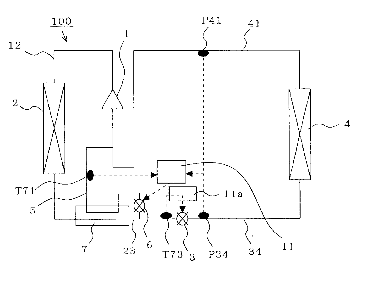
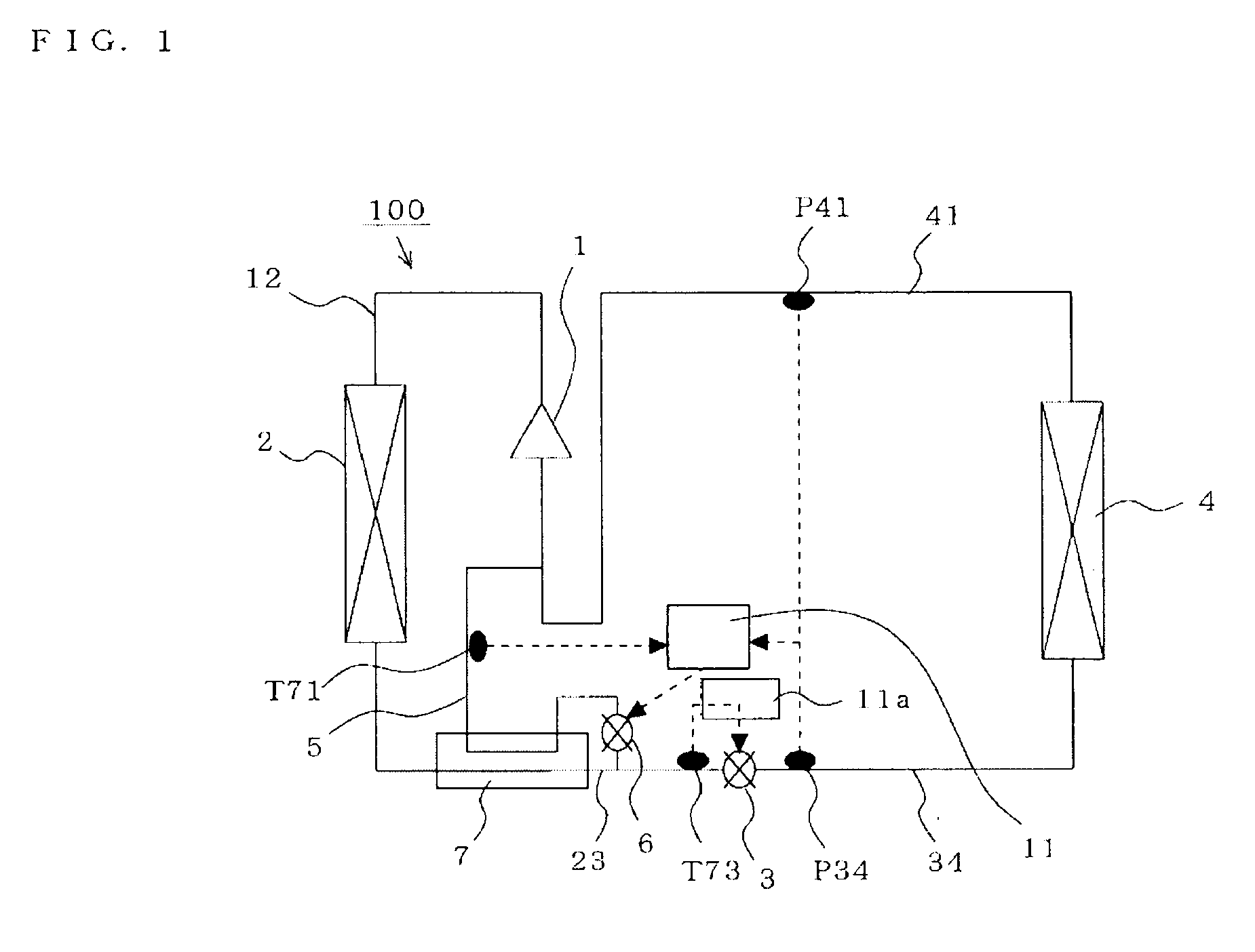
[0033]FIG. 1 is a refrigerant circuit diagram illustrating the configuration of a refrigeration cycle device according to a first embodiment of the present invention. In FIG. 1, the refrigeration cycle device 100 includes a main circuit that is equipped with a compressor 1 that compresses a refrigerant; a condenser 2 that condenses the compressed refrigerant; an expansion valve (a flow control valve such as an electronic expansion valve, a capillary tube, or the like) 3 that expands the condensed refrigerant; an evaporator 4 that evaporates the expanded refrigerant; a high-temperature / high-pressure pipe 12 that connects the compressor 1 to the condenser 2; a medium-temperature / high-pressure pipe 23 that connects the condenser 2 to the expansion valve 3; a low-temperature / low-pressure pipe 34 that connects the expansion valve 3 to the evaporator 4; and a medium-temperature / low-pressure pipe 41 that connects the evaporator 4 to the compressor 1.

[0034]In addi...

second embodiment

Control Method

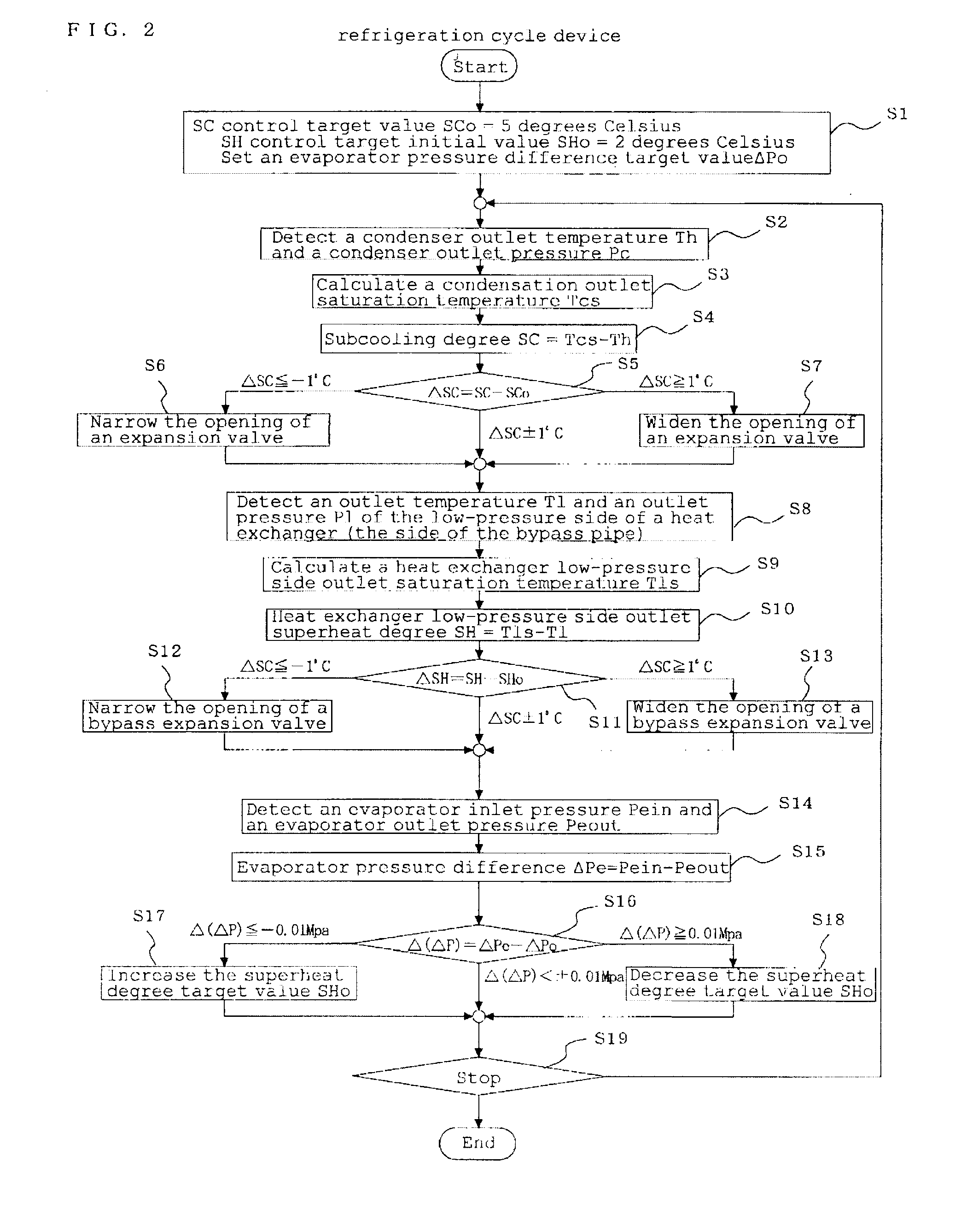
[0047]The following describes the control of the expansion valve 3 and the bypass expansion valve 6 by the control means of the refrigeration cycle device illustrated in the first embodiment, with reference to FIG. 2.

[0048]FIG. 2 is a flowchart showing the subcooling degree control and superheat degree control processes by the control means and is used to illustrate the method of controlling the refrigeration cycle device of the second embodiment of the present invention.

[0049]In FIG. 2, the subcooling degree control section 11a and the superheat degree control section 11b first set initial values (SCo=5 degrees Celsius and SHo=2 degrees Celsius, for example) as a subcooling degree target value SCo and a superheat degree target value SHo, respectively (S1). The initial values are those appropriately adjusted according to installation conditions and type of the refrigeration device (a positive value greater than or equal to zero) and are stored in advance in a nonvolati...

third embodiment

[0099](Refrigeration Cycle)

[0100]FIG. 5 is a refrigerant circuit diagram illustrating the configuration of a refrigeration cycle device according to a third embodiment of the present invention. In FIG. 5, a refrigeration cycle device 200 is formed by adding a gas-liquid separator 8 to the low-temperature / low-pressure pipe 34 of the refrigeration cycle device 100 (First Embodiment) and providing a pipe (referred to as “gas pipe,” hereinafter) 10 that supplies a gas (vapor) separated by the gas-liquid separator 8 to the compressor 1.

[0101]A flow control valve (referred to as “gas flow control valve,” hereinafter) 9 is provided midway of the gas pipe 10. A gas flow control valve inlet pressure sensor P89 and a gas flow control valve outlet pressure sensor P91 are provided at the upstream and downstream sides of the gas flow control valve 9, respectively.

[0102]Incidentally, the configuration of the other portions is the same as that of the refrigeration cycle device 100 (First Embodimen...


PUM


Abstract

A refrigeration cycle device 100 where a combustible refrigerant circulates includes a bypass pipe 5 that is connected so that part of the refrigerant that flows through a circulation pipe extending from a condenser 2 to a flow control valve 3 bypasses the flow control valve 3 and an evaporator 4; a bypass flow control valve 6 that controls the amount of the refrigerant flowing through the bypass pipe 5; a heat exchanger 7 that allows heat exchange between the refrigerant that flows through the bypass pipe 5 after flowing out of the bypass flow control valve 6 and the refrigerant that flows through the circulation pipe after flowing out of the condenser 2; and a subcooling degree sensor T73 that detects the subcooling degree of the refrigerant at the inlet of the flow control valve 3. At least either the flow control valve 3 or the bypass flow control valve 6 is controlled so that the subcooling degree of the refrigerant at the inlet of the flow control valve 3 is equal to or greater than or a predetermined value.

Description

TECHNICAL FIELD[0001]The present invention relates to a refrigeration cycle device, and more particularly to a refrigeration cycle device that uses a refrigerant having a small Global Warming Potential.BACKGROUND ART[0002]A conventional refrigeration cycle device is formed by connecting the following components in the following order through refrigerant pipes: a compressor that compresses a medium-temperature low-pressure refrigerant (referred to as “medium-temperature / low-pressure,” hereinafter for ease of explanation); a condenser that condenses the compressed refrigerant (referred to as “high-temperature / high-pressure refrigerant,” hereinafter); an expansion valve that expands the condensed refrigerant (referred to as “medium-temperature / high-pressure refrigerant,” hereinafter); and an evaporator that evaporates the expanded refrigerant (referred to as “low-temperature / low-pressure refrigerant,” hereinafter). Hereinafter, such configuration is referred to as “main circuit.” An in...

Claims


Application Information

Patent Timeline
IPC IPC(8): F25B1/00F25B41/04F25B41/00F28D15/04F25B43/00
CPCF24F2011/0084F25B41/00F25B2400/12F25B2400/13F25B40/02F25B2600/2509F25B2700/21F25B2341/063F25B2500/19F24F11/36F25B40/06F25B2341/064F25B2400/0419
Inventor WAKAMOTO, SHINICHIUNEZAKI, FUMITAKEKURAMOCHI, TAKESHIIIJIMA, HITOSHI
Owner MITSUBISHI ELECTRIC CORP
Why Eureka
Try Eureka