
Payload Stowage Unit

a stowage unit and payload technology, applied in the field of external stowage units, can solve the problem that venturing to the environment is often not desired

Inactive Publication Date: 2011-04-14
BABCOCK INTEGRATED TECH LTD
View PDF9 Cites 8 Cited by
  • Summary
  • Abstract
  • Description
  • Claims
  • Application Information

AI Technical Summary

Benefits of technology

"The present invention proposes a payload stowage unit for a marine vessel that allows for the storage and deployment of a weapon, countermeasure, or unmanned underwater vehicle (UUV) without venting to the environment. The unit includes an outer vessel, an inner tube for holding the payload, and a valve that allows fluid communication between the inner tube and the outer vessel. The inner tube can move within the outer vessel, and the sealing elements are positioned at either end of the volume to seal it. The stowage unit can be connected to an externally mounted power supply and may have an externally mounted launch control. The technical effects of this invention include the ability to store and deploy payloads without venting to the environment, the ability to maintain the weight of the system at about the same level before and after deployment, and the ability to operate the stowage unit entirely self-contained without physical communication with the pressure hull."

Problems solved by technology

Venting to the environment is often not desired as it can cause the position of the submarine to become known.

Method used


Image

  • Payload Stowage Unit
  • Payload Stowage Unit
  • Payload Stowage Unit

Examples


Embodiment Construction

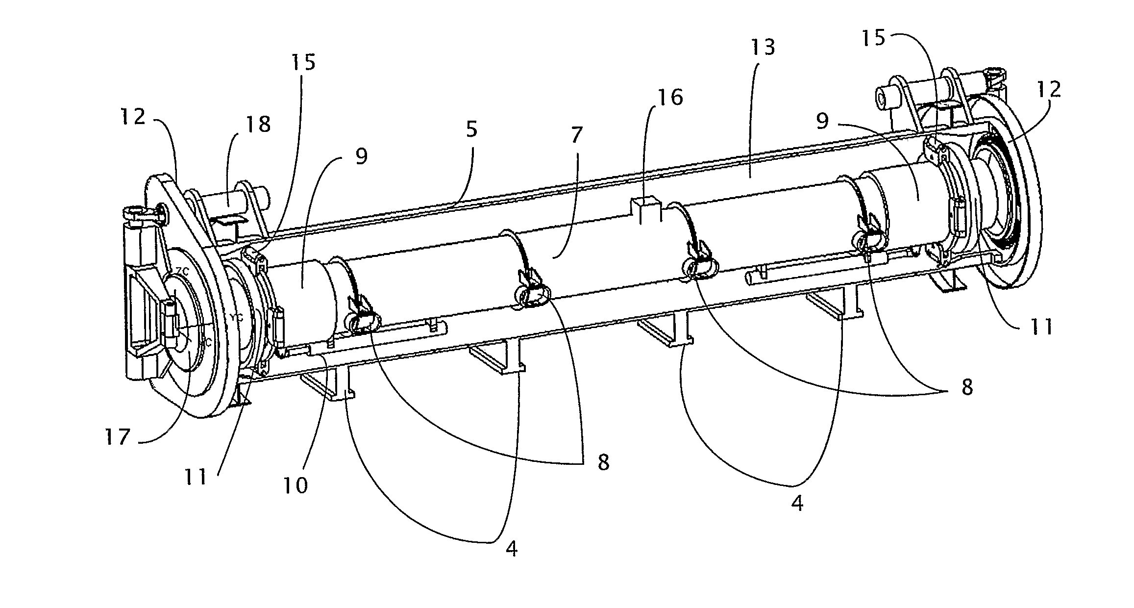
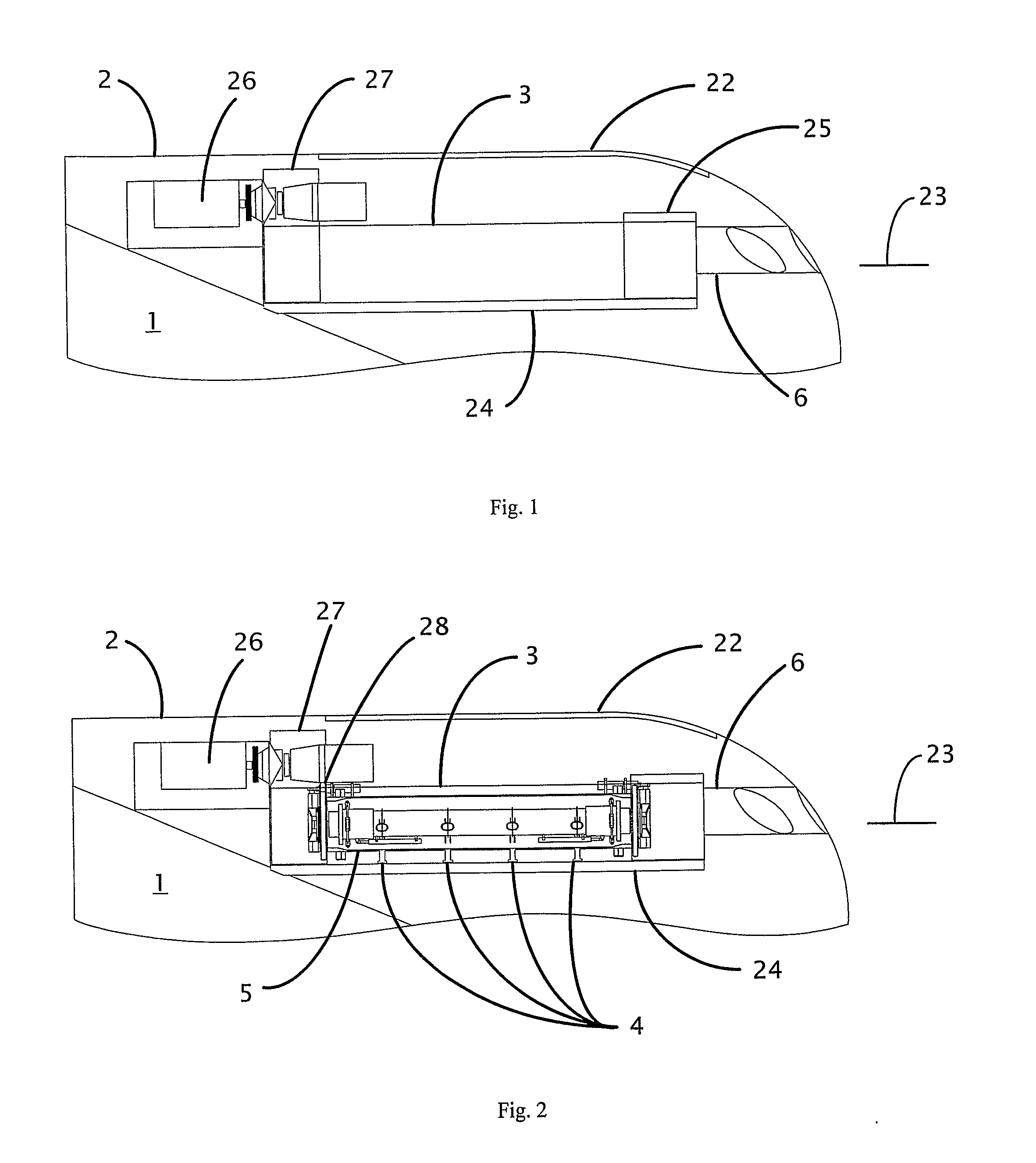
[0044]In an embodiment of the present invention the external stowage unit is installed between the pressure hull 1 and the outer casing 2 of a double-hulled submarine. The stowage unit is accessed via casing closure plate 22. The pressure hull 1 resists external hydrostatic pressure and creates a watertight compartment, whilst the outer casing 2 gives the submerged submarine a hydrodynamic shape. The estimated water line when the submarine is surfaced is indicated by reference numeral 23.

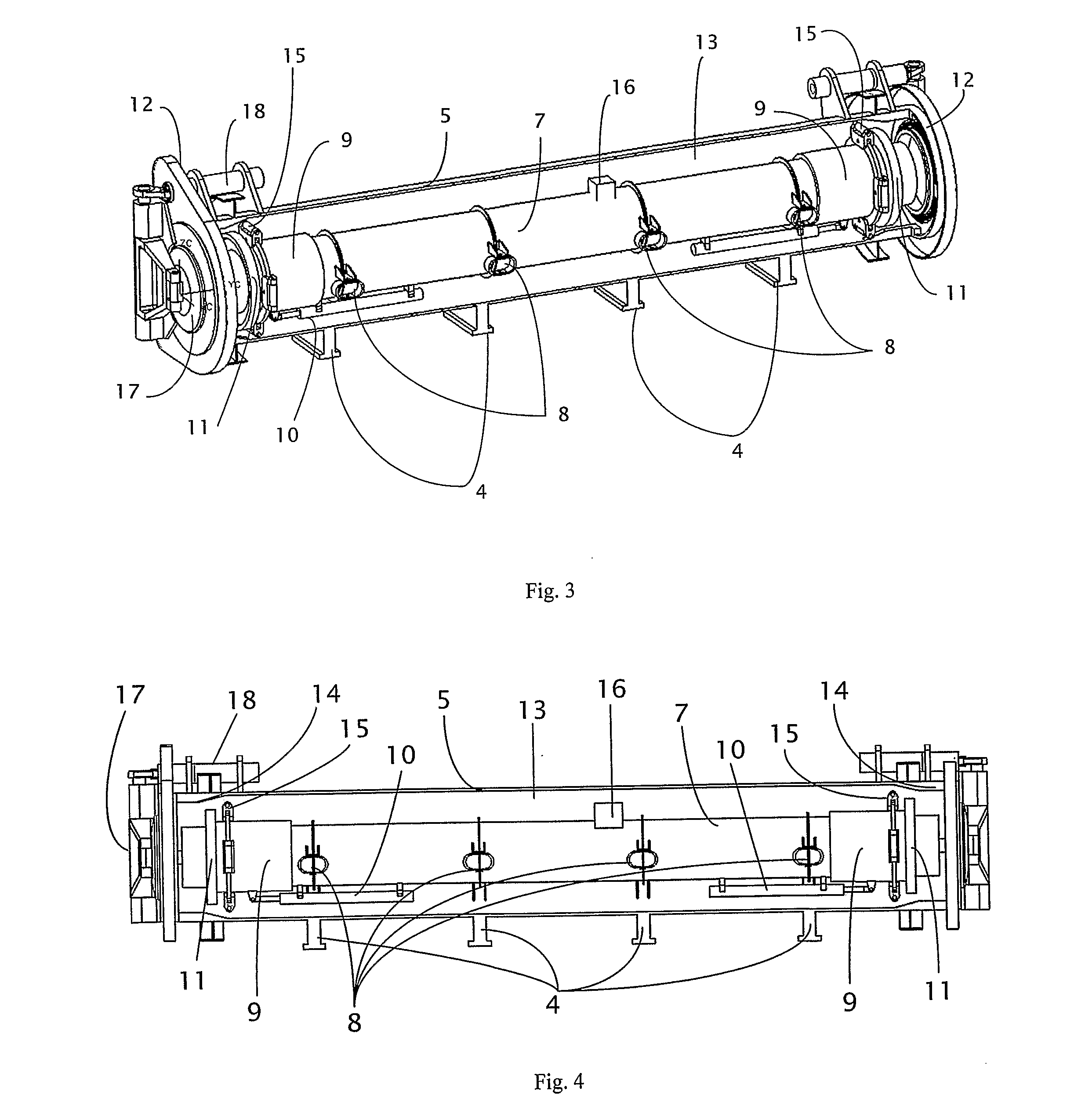
[0045]In the present embodiment the stowage unit is fastened within a coffer dam 3 in a forward-pointing position by means of fastening struts 4 that project from the outer tube 5 of the stowage unit. The coffer dam may be omitted in other embodiments. Deployment of the stowed payload is through a shutter 6 in the outer casing 2 of the submarine. Optionally, the submarine has no outer casing and the stowage unit is attached directly to the pressure hull. Other arrangements of positioning the stowage...


PUM


Abstract

A stowage unit for a payload such as a weapon, countermeasure or unmanned underwater vehicle (UUV), and a method for using the unit to deploy the payload are described. The unit comprises an inner tube for holding the payload, wherein the inner tube is mounted in an outer vessel and so defines a volume between the outer vessel and inner tube. The volume has a first sealing element, which can be used to open or seal the volume at one end, and a valve enabling fluid communication between the volume and inner tube. After deployment of the payload, a weight of fluid equivalent to the deployed payload can be allowed to enter the volume from the inner tube, thus enabling the weight of the unit to remain substantially unaltered from before deployment to after deployment.

Description

BACKGROUND OF THE INVENTION[0001]1. Field of the Invention[0002]The present invention relates to an external stowage unit for a payload such as a weapon, countermeasure or unmanned underwater vehicle (UUV). It also relates to marine vessels incorporating such a stowage unit, and in particular, submarines incorporating such a stowage unit.[0003]2. Summary of the Prior Art[0004]Stowage units are known for storing weapons or countermeasures on marine vessels. Such units typically include an openable container for holding the weapon or countermeasure which, when closed, forms a ‘dry volume’ that protects the contents from the external environment. In some instances the container is mounted within a larger volume such that it can move within the larger volume. Such ‘shock-mounting’ shields the stowed weapon or countermeasure from impulsive accelerations. An embodiment of this concept is the ‘tube within a tube’ where a conventionally sized torpedo tube is shock-mounted within a larger tu...

Claims


Application Information

Patent Timeline
Patent Type & Authority Applications(United States)
IPC IPC(8): B63G8/22B63G8/00
CPCB63G8/28F41F3/10B63G8/32
Inventor WHITTEN, TIMOTHY JAMESCARTER, NICHOLAS JOHN
Owner BABCOCK INTEGRATED TECH LTD
Learn More