Device with co-molded closure, one-way valve and variable-volume storage chamber, and related method

a technology of one-way valve and storage chamber, which is applied in the direction of check valves, rigid containers, packaging, etc., can solve the problems of relatively high manufacturing cost, relatively high device cost, etc., and achieve the effect of preventing any ingress, easy assembly and convenient assembly

Active Publication Date: 2011-04-14
DR PY INST LLC
View PDF16 Cites 54 Cited by
  • Summary
  • Abstract
  • Description
  • Claims
  • Application Information

AI Technical Summary

Benefits of technology

[0026]One advantage of the device and method of the present invention, and / or of the currently preferred embodiments thereof, is that the closure, valve cover and actuator can be co-molded as a single part, the base defining the valve seat, compression chamber and variable-volume storage chamber pre-form can be injection molded as a single part, and therefore the device can be formed in essentially two parts that can be easily assembled, such as by snap fitting the closure to the base. Accordingly, the device can be manufactured with significantly fewer parts than prior art devices, yet can exhibit comparable or even greater functionality than such prior art devices.
[0027]Another advantage of the preferred embodiments is that the device and method allow the capacity to fill viscous products and to re-seal at room temperature, even over a residue, due to the cavity being made for the purpose of sealing, and being made of the same material or substantially the same material as the sealant.
[0028]Another advantage of the currently preferred embodiments is the self resealing property of the elastic and the relatively thick silicone dome actuator which prevents any ingress after filling. As a result, the sterile filling machine used to fill the device may be relatively inexpensive, whether it includes a laser for resealing, and / or involves the assembly of an additional part for mechanically resealing the resulting penetration aperture.
[0029]Another substantial advantage of the preferred embodiments is that the valve is extremely simple, and the tension only of the elastic valve segment after assembly onto the second support allows the valve characteristics to be adjusted to the viscosity of the product to be sealed within the device and dispensed through the valve. Any residue left in between the valve and the underlying nozzle is forced out by the interference / hoop stress differential between the valve and nozzle from the base to the dispensing tip of the valve.
[0030]Another advantage of the currently preferred embodiments is that the elastic valve member is easy to assemble onto the rigid underlying nozzle of the enclosure and thereby provides a high quality product at a relatively inexpensive cost.
[0031]Another substantial advantage of the preferred embodiments is the possibilities offered by the relatively thin wall of the stretched blow molded pouch, and as a consequence, the extremely small amount of plastic needed to form the liquid container itself, which may be made of only two pieces. Yet another advantage is that the outer housing or recipient can be made out of a fully bio degradable material, of a re-usable material and / or an entirely recyclable material, knowing that the enclosure can be disassembled automatically from the outer recipient.

Problems solved by technology

Such devices can be relatively expensive, and their manufacture relatively time consuming and expensive.

Method used


Image

  • Device with co-molded closure, one-way valve and variable-volume storage chamber, and related method
  • Device with co-molded closure, one-way valve and variable-volume storage chamber, and related method
  • Device with co-molded closure, one-way valve and variable-volume storage chamber, and related method

Examples


Embodiment Construction

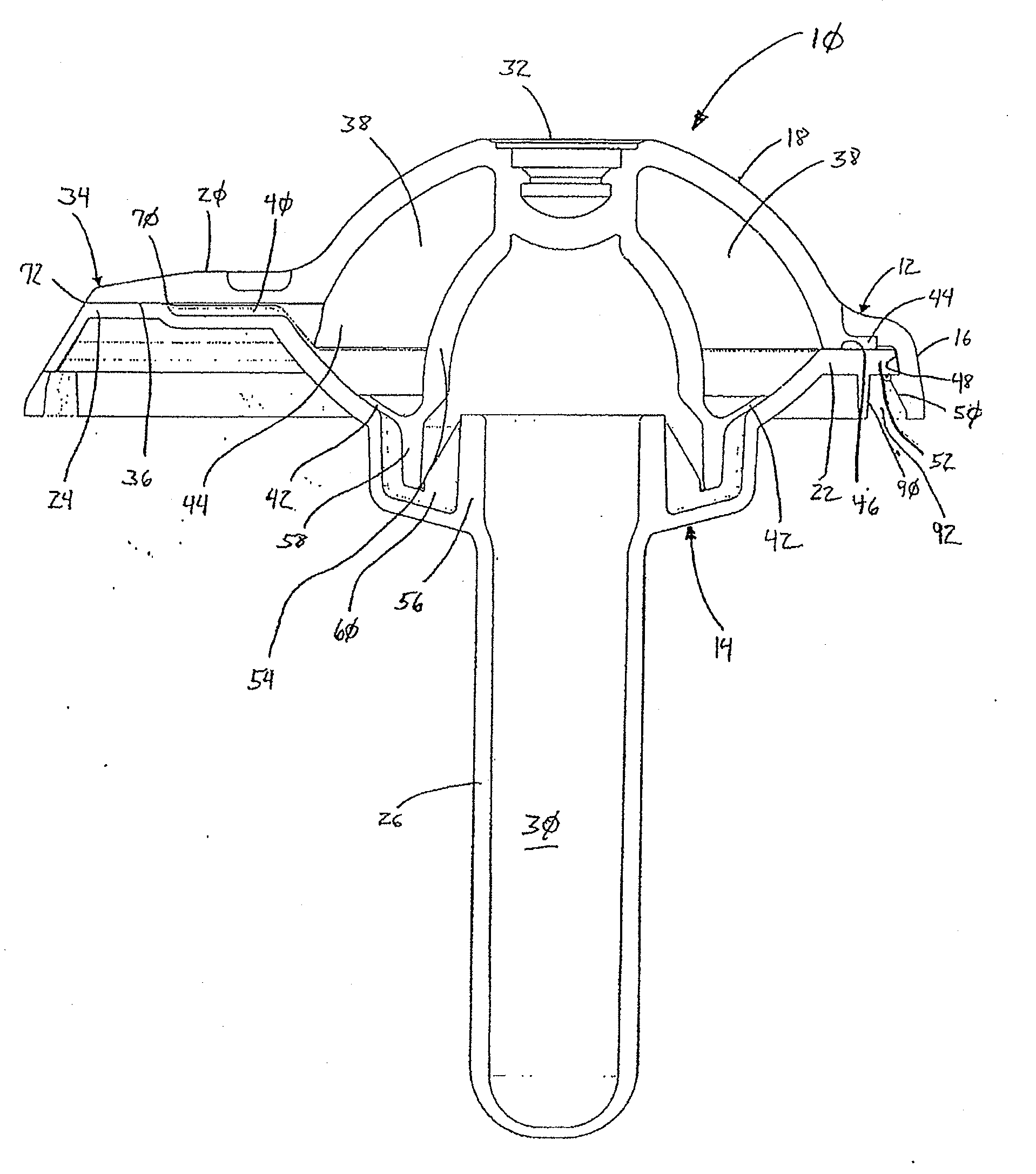
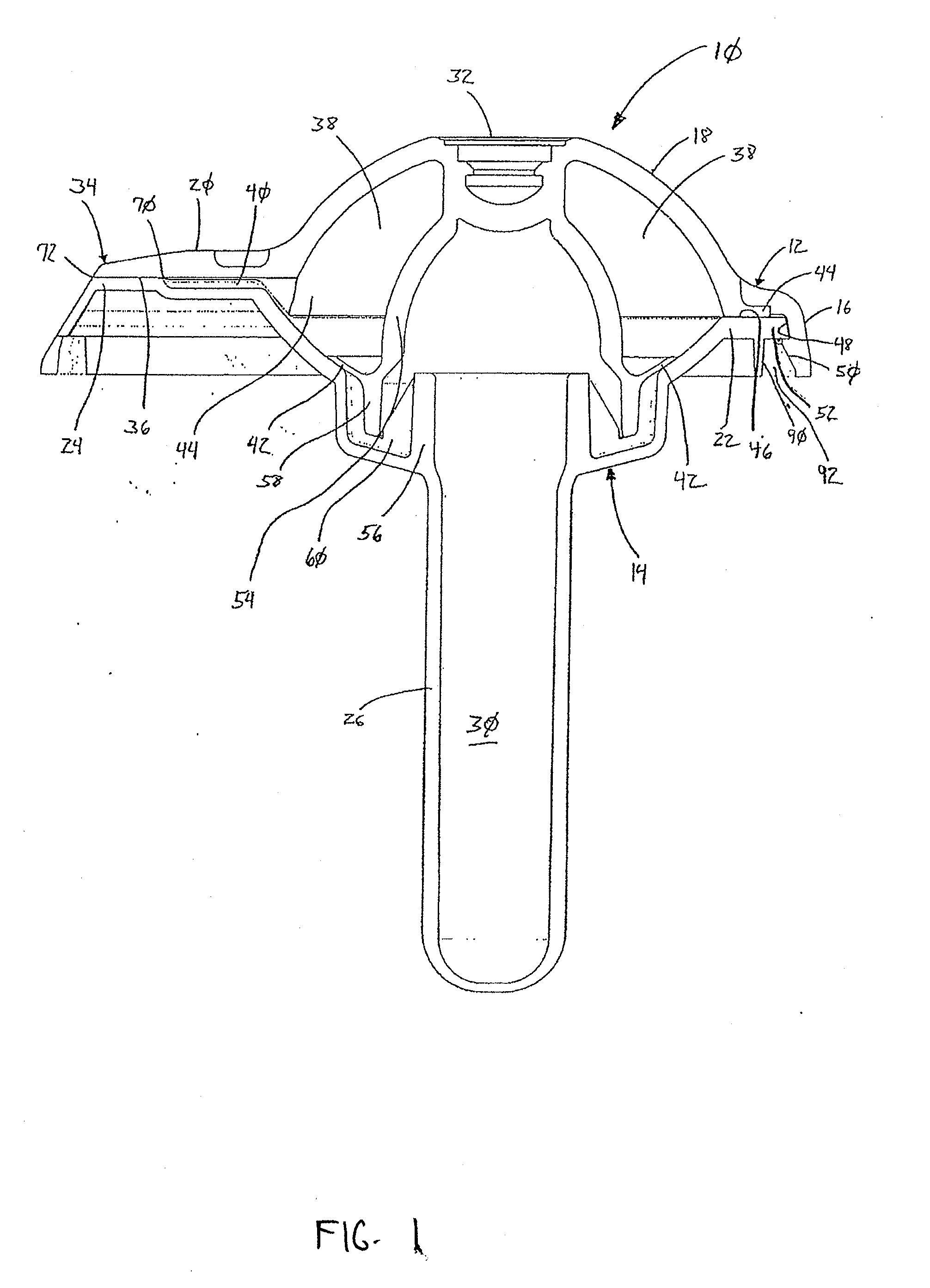
[0043]In FIGS. 1-10, a device embodying the present invention is indicated generally by the reference numeral 10. The device 10 includes a first piece 12 that is secured to a second piece 14 to form a sealed, empty device. The first piece 12 defines an integral first support 16, actuator 18 and flexible one-way valve or valve cover 20. The components of the first piece 12 are co-molded, such as by injection molding the first support 16, and over molding the actuator 18 and valve cover 20 to the first support 16. The second piece 14 includes a second support 22, a valve seat or nozzle 24, and a variable-volume storage chamber pre-form 26. As described further below in connection with FIG. 2, the pre-form 26, but not the second support 22 and valve seat 24, is blow molded into a flexible pouch defining a variable-volume storage chamber 30.

[0044]The first piece 12 further defines a recess 32, which as described further below in connection with FIGS. 7 and 8, defines a needle penetrable...


PUM

PropertyMeasurementUnit
pressureaaaaaaaaaa
flexibleaaaaaaaaaa
creepaaaaaaaaaa

Abstract

A device includes a first part having a co-molded first support, valve cover and elastic actuator, and a second part having an injection molded second support, valve seat, and variable-volume storage chamber pre-form. The pre-form is blow molded into a flexible pouch defining the variable-volume storage chamber. The one-way valve includes a semi-annular, curvilinear, relatively rigid valve seat defining axially-extending, opposing first marginal portions, and an axially-extending first mid-portion angularly extending between the opposing first marginal portions. A flexible valve member is superimposed on the valve seat and defines axially-extending, opposing second marginal portions fixedly secured on or adjacent to respective first marginal portions of the valve seat, and an axially-extending second mid-portion angularly extending between the opposing first marginal portions and superimposed onto the first mid-portion of the valve seat. The flexible valve cover and valve seat form a normally closed axially and angularly extending valve seam therebetween.

Description

CROSS-REFERENCE TO RELATED APPLICATIONS[0001]This patent application claims priority to U.S. Provisional Patent Application Ser. No. 61 / 250,363, entitled “Device with Co-Molded Closure, One-Way Valve and Variable-Volume Storage Chamber, and Related Method,” filed Oct. 9, 2009, which is hereby expressly incorporated by reference in its entirety as part of the present disclosure.FIELD OF THE INVENTION[0002]The present invention relates to devices with one-way valves and variable-volume storage chambers, and more particularly, to new and improved one-way valves, devices including one-way valves and / or variable-volume storage chambers, and to related methods.BACKGROUND INFORMATION[0003]Prior art devices including one-way valves and variable-volume storage chambers require the separate manufacture of the one-way valves, the closures, the variable-volume storage chambers, and the housings for receiving therein one or more such components. Such prior art devices require the separate manufa...

Claims


Application Information

Patent Timeline
Patent Type & Authority Applications(United States)
IPC IPC(8): B65D37/00F16K15/00B29C49/06B29C69/02B29C49/00
CPCB29B11/08B29B2911/1452B29B2911/1402B29B2911/14026B29B2911/14033B29B2911/1404B29B2911/14053B29B2911/14066B29B2911/1408B29B2911/14093B29B2911/14106B29B2911/14113B29B2911/14133B29B2911/1414B29B2911/14326B29B2911/14333B29B2911/1442B29B2911/14473B29C49/06B29K2023/12B29K2067/00B29K2105/258B65D83/0061F16K15/147B65B55/08B29B11/14B29C2949/3016B29C2949/302B29C2949/3008B29C2949/3012B29C2949/28B29C2949/24B29C2949/26B29C2949/22B29C2949/3024B29C2949/3026B29C2949/3032B29C2949/3034B29C2949/072B29C2949/073B29C2949/077B29C2949/0778B29C2949/0792Y10T137/7837B29C49/071B29C2949/0715B29C2049/023B05B11/047B65D47/2081B65D47/04B65D77/06B65D51/002F16K15/1401B65B51/023B29C73/025
Inventor PY, DANIEL
Owner DR PY INST LLC
Why Eureka
Try Eureka