Method and device for particle analysis using thermophoresis
a particle analysis and thermophoresis technology, applied in the field of thermophoresis characterisation of particles, can solve the problems of high setup cost, limited use of electrophoresis to charge panicles, and time-consuming preparation
- Summary
- Abstract
- Description
- Claims
- Application Information
AI Technical Summary
Benefits of technology
Problems solved by technology
Method used
Image
Examples
example 1
Determination of Sorer Coefficient in & Setup with a One-Dimensional Temperature Gradient
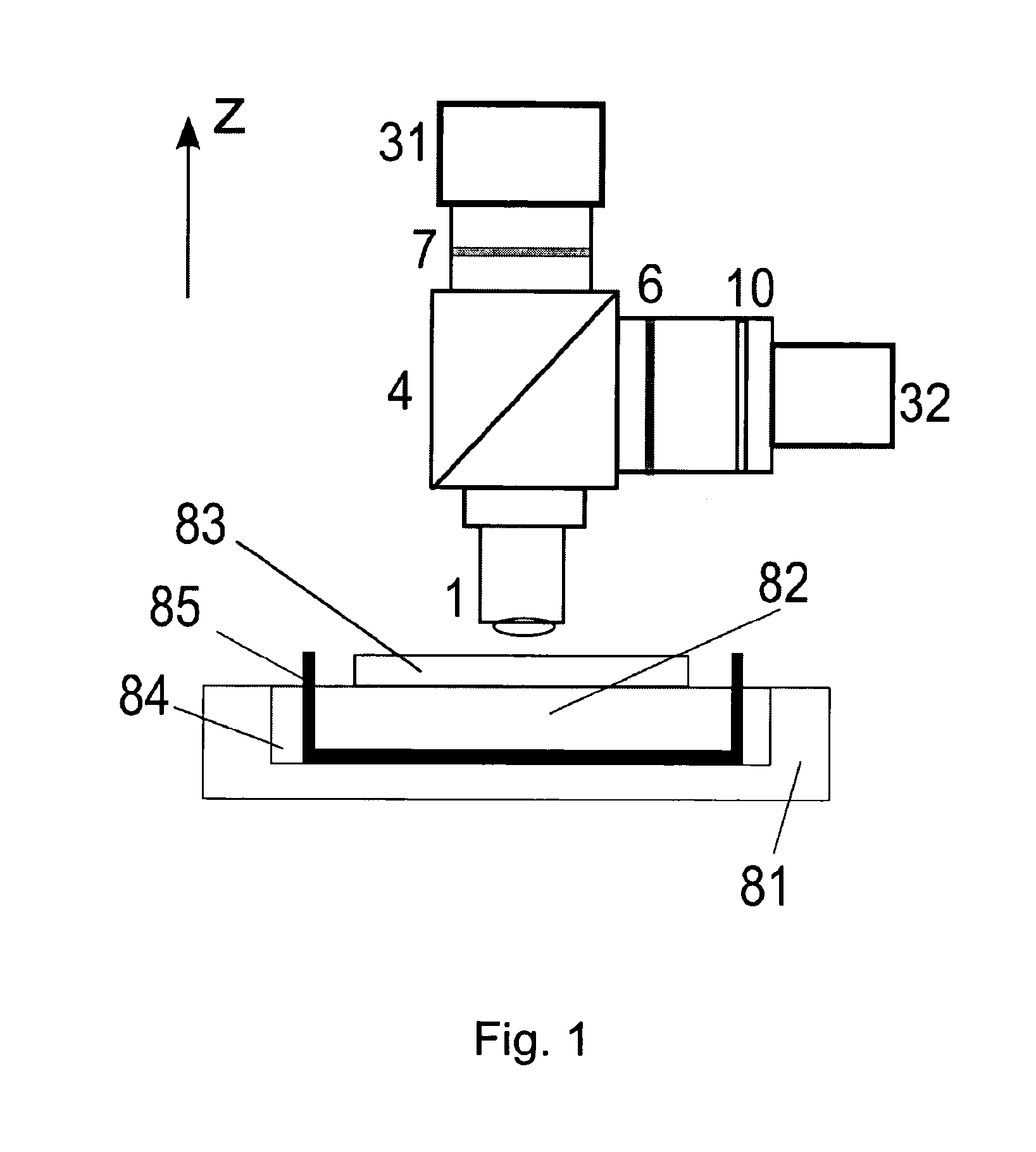
[0203]Before an actual measurement the base plate of a measurement chamber is attached to a cooling device and the cap or cover lid of the measurement chamber is attached to the heating element with high thermal conductive glue. These fixings can be permanent or removable, but the glue used for permanent fixing is preferably resistant against solvents like ethanol or isopropanol as the cap and the base plate are preferably cleaned after each measurement.
[0204]After fixing the cooling device to the base plate and the heating element to the cap, the chamber confinements are brought onto the base plate. According to a preferred embodiment, the confinements are made of a thin foil or layer with a recess or hole for the chamber. Thus the height of this foil determines the measurement chamber's height. The foil adheres to the base plate and any air enclosed under the foil is removed by pressing the fo...
example 2
Determination of Soret Coefficient in a Setup with a Vertical Heating Structure
[0214]Step 1a, Background Measurement:
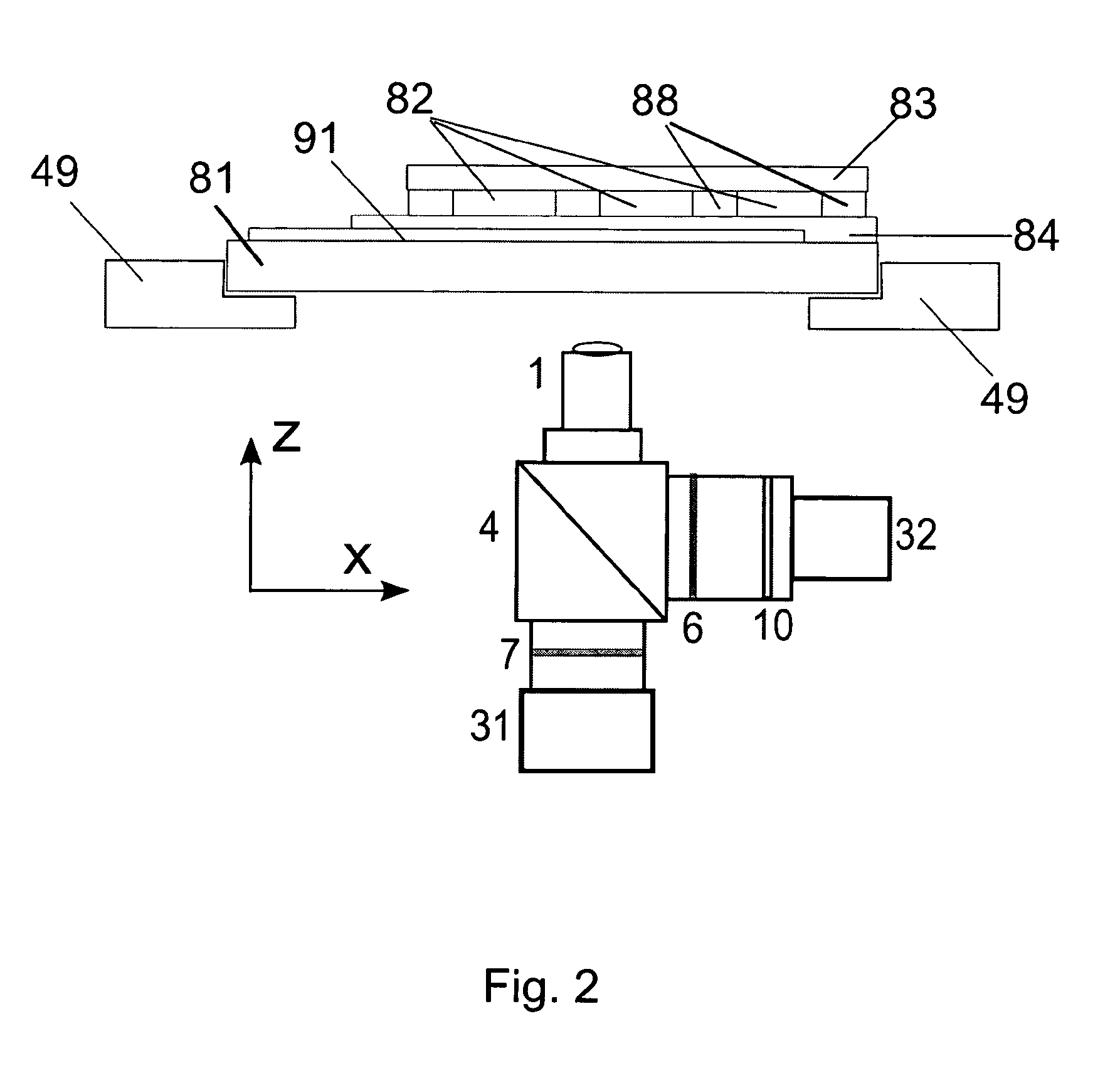
[0215]A sample buffer (sample probe) without fluorescently marked sample molecules-particles is filled in a microfiuidic chamber containing a central heating wire which is parallel to the direction of the fluorescence detection. The heating wire is positioned in the center of the chamber and extends through the wall of the microfiuidic chamber. The wire is preferably fixed to the chamber wall by glue, which is resistant to water and organic solvents. After a few microliter of the sample solution containing only buffer is filled into the chamber, it is sealed by putting a cover lid on the opening on top. The height of the chamber (i.e. in direction of the heating wire; distance between cover slip and the bottom plate) is less than 500 μm preferably Seas than 100 μm and care should be taken that the height of the chamber is the same if results measured in different cham...
example 3
Determination of Hydrodynamic Radius in a Setup with a Vertical Heating Structure
[0224]The thermo-optical characterization method allows also to quantify the hydrodynamic radius of proteins / nanoparticles and even more important of complexes of biomolecules (which are not connected covalently to each other). Thermophoresis provides a comparably robust and precise way to measure the hydrodynamic radius of molecules from less than a nanometer up to a few microns. This thermo-optical characterization method can also be used in complex fluids as there are to mention blood, blood serum and cell lysate fox example, in which state of the art techniques face problems
Data Acquisition:
[0225]A typical measurement can be described as follows:
Step 1:
[0226]A solution of fluorescently labeled molecules (e.g. Quantum dots; excitation 480 nm, emission 650 nm) is filled into a microfluidic measurement, chamber containing a vertical, heating wire (parallel to the direction of fluorescence detection). T...
PUM
 Abstract
Description
Claims
Application Information
 - R&D
- Intellectual Property
- Life Sciences
- Materials
- Tech Scout
- Unparalleled Data Quality
- Higher Quality Content
- 60% Fewer Hallucinations
Browse by: Latest US Patents, China's latest patents, Technical Efficacy Thesaurus, Application Domain, Technology Topic, Popular Technical Reports.
© 2025 PatSnap. All rights reserved.Legal|Privacy policy|Modern Slavery Act Transparency Statement|Sitemap|About US| Contact US: help@patsnap.com


