Wedge threads with a solid lubricant coating

a technology of solid lubricant coating and wedge thread, which is applied in the direction of hose connection, screw threaded joint, manufacturing tools, etc., can solve the problems of limiting the make-up speed of the connection, damage to the connection, and insufficient make-up

Inactive Publication Date: 2011-04-14
HYDRIL CO
View PDF42 Cites 10 Cited by
  • Summary
  • Abstract
  • Description
  • Claims
  • Application Information

AI Technical Summary

Problems solved by technology

When a wedge thread connection is made-up, excess pipe dope may become trapped (rather than being squeezed out) between the pin threads and the box threads, which may either cause false elevated torque readings (leading to insufficient make-up or “stand-off”) or, in certain circumstances, damage the connection.
However, limiting the make-up speed of the connection slows down the overall process of assembling the drillstring.
Pipe stand-off due to inadequate evacuation of pipe dope is detrimental to the structural integrity of wedge thread connections.
As the pressure build-up may bleed off during use, the connection is at risk of accidentally backing-off during use.
Therefore, stand-off in wedge thread connections is of particular concern as it may lead to loss of seal integrity or even mechanical separation of two connected members.
Furthermore, pipe stand-off may be particularly problematic in strings used at elevated downhole service temperatures (i.e., the temperature a tubular would be expected to experience in service).
Particularly, in high temperature service (e.g., temperatures greater than 250° F., a steam-flood string, or a geothermal string), even a small amount of stand-off may be deleterious.
For example, if a made up wedge thread connection having even an infinitesimal amount of stand-off is deployed to a high temperature well, the pipe dope may flow out of the wedge thread connection, thus reducing the integrity of the thread seal.
Further, use of a flowing pipe dope in wedge threads may lead to thread seal leaks, particularly at elevated pressures, as the viscosity of the pipe dope increases.
Because of the length and configuration of the wedge thread, the larger diameter connections may be susceptible to hydraulic lock and require extra torque to push the thread dope (i.e., force the thread dope to flow) along the length of the connection.
Notably, double bumping increases connection make-up time.

Method used


Image

  • Wedge threads with a solid lubricant coating
  • Wedge threads with a solid lubricant coating
  • Wedge threads with a solid lubricant coating

Examples


Embodiment Construction

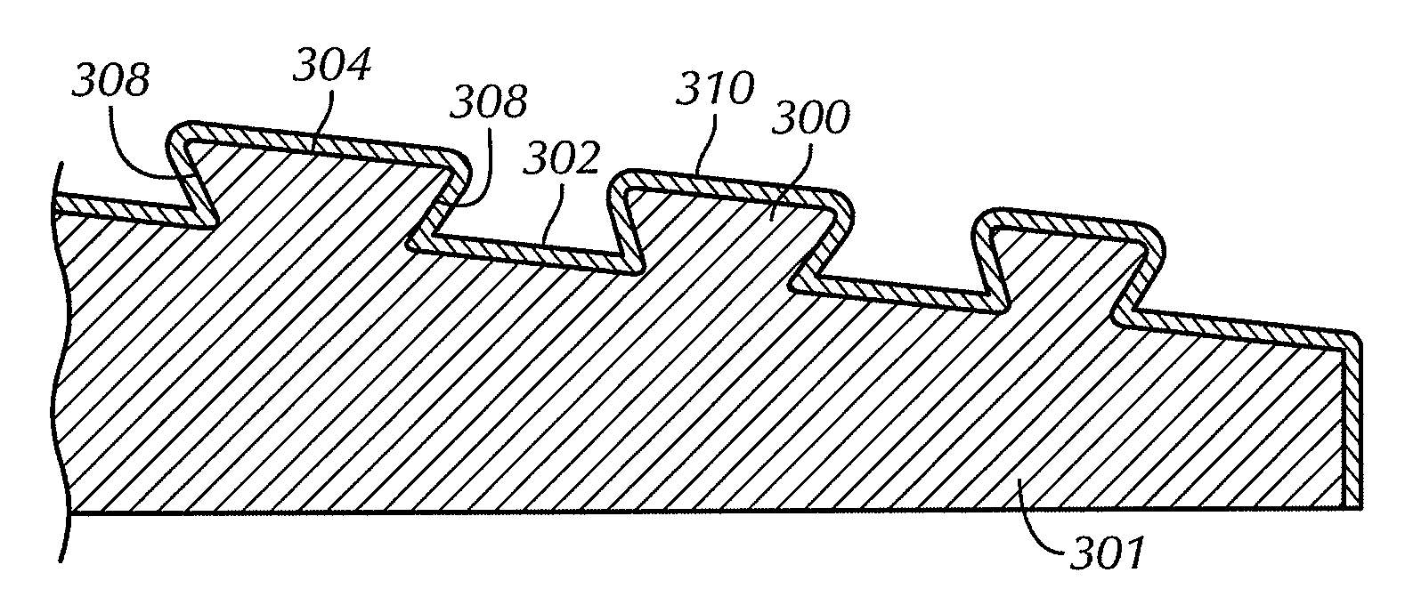
[0021]In one aspect, embodiments disclosed herein relate to a wedge thread connection with a solid lubricant coating permanently bonded thereon and related methods of permanently bonding the solid lubricant coating to the wedge threads. The threaded connection may include a corresponding pin member and box member having wedge threads formed thereon. The solid lubricant coating may be permanently bonded on the pin member, the box member, or both the pin and box members prior to make-up of the connection. One or more layers of the solid lubricant coating may be used depending on the type of end configurations of the connection (i.e., full length pin, full length box, or coupling).

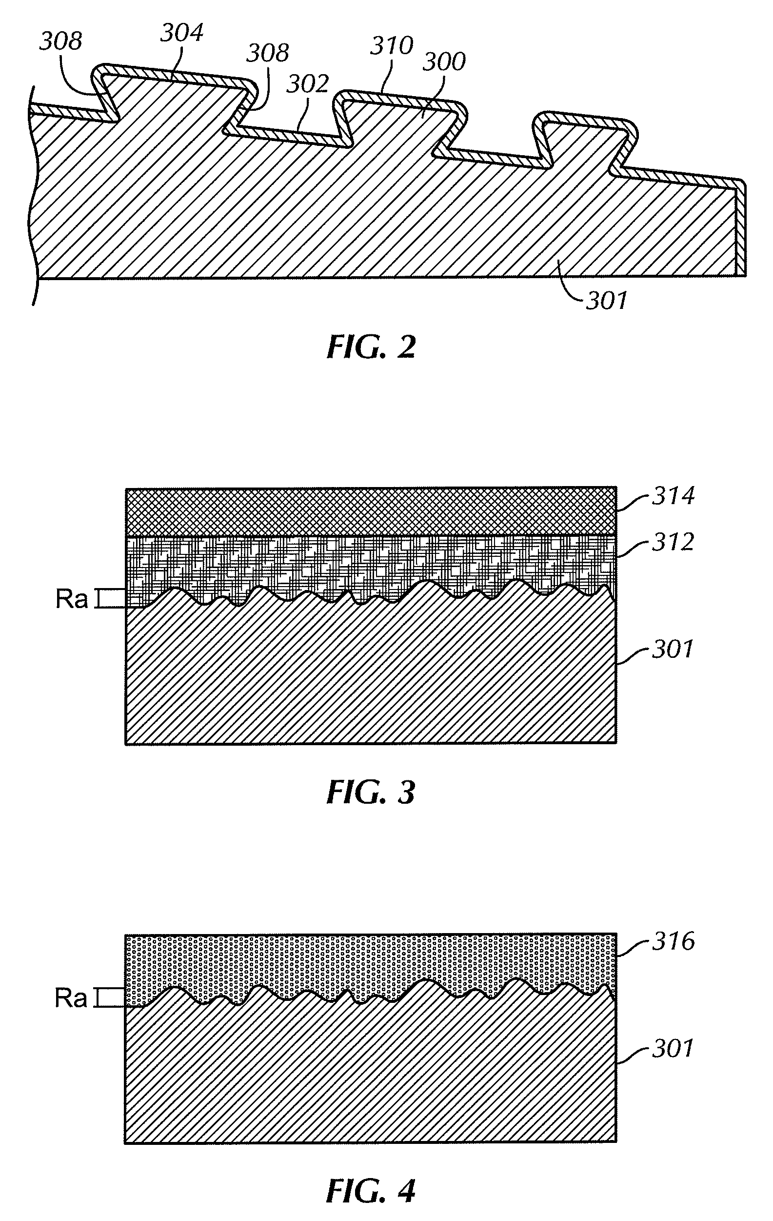
[0022]Referring now to FIG. 2, a cross-sectional view of a wedge thread 300 having a solid lubricant coating 310 permanently bonded thereon is shown in accordance with embodiments of the present disclosure. The wedge thread 300 is formed on a tubular member 301, which may be either a pin member or box member....


PUM

PropertyMeasurementUnit
thicknessaaaaaaaaaa
thicknessaaaaaaaaaa
thicknessaaaaaaaaaa

Abstract

A tubular connection includes a pin member having external wedge threads configured to engage a box member having corresponding internal wedge threads, and a solid lubricant coating applied on at least one of the internal and external wedge threads wherein the solid lubricant coating comprises a first uniform layer of a dry corrosion inhibiting coating made of an epoxy resin containing particles of zinc and a second uniform layer of a dry lubricant coating covering the first uniform layer.

Description

CROSS-REFERENCE TO RELATED APPLICATIONS[0001]This application claims priority, under 35 U.S.C. §119(e), to U.S. Patent Application No. 61 / 251,124, filed on Oct. 13, 2009, which is assigned to the present assignee and herein incorporated by reference in its entirety.BACKGROUND[0002]1. Field of the Disclosure[0003]Embodiments disclosed herein relate generally to wedge thread connections. More particularly, embodiments disclosed herein relate to wedge threads having a solid lubricant coating permanently bonded thereon and related methods of permanently bonding the solid lubricant coating on the wedge threads.[0004]2. Background Art[0005]One type of threaded connection commonly used in oil country tubular goods is known as a wedge thread. Referring initially to FIGS. 1A and 1B, a prior art tubular connection 100 having a wedge thread is shown. As used herein, “wedge threads” are threads, regardless of a particular thread form, that increase in width (i.e., axial distance between load fl...

Claims


Application Information

Patent Timeline
Patent Type & Authority Applications(United States)
IPC IPC(8): F16L58/04F16L15/06B23P17/00
CPCF16L15/001C10N2250/08C10M2209/104Y10T29/49888F16L15/06C10M145/28B21C23/24E21B17/042C10N2050/08
Inventor MALLIS, DAVID LLEWELLYNREADE-ROMERO, ANDREA L.
Owner HYDRIL CO
Why Eureka
Try Eureka