
Low profile, surface-mounted power generation system

a power generation system and low-profile technology, applied in the direction of machines/engines, mechanical equipment, roads, etc., can solve the problems of limited practicality of vehicle energy harvesting devices, few devices that capture energy from passing vehicles, etc., and achieve the effects of short payback period, simple installation, and scalable configuration

Inactive Publication Date: 2011-04-14
SOLARWINDOW TECH
View PDF86 Cites 5 Cited by
  • Summary
  • Abstract
  • Description
  • Claims
  • Application Information

AI Technical Summary

Benefits of technology

The present invention provides a novel vehicle energy harvester that overcomes many of the problems with conventional devices and is better suited for real-world implementation. The invention can absorb mechanical energy from passing vehicles and convert the mechanical energy to electrical energy using, for example, shaft driven generators. The invention is simple to install, provides a short payback period, and has a scalable configuration. The low cost configuration of the system may provide faster payback of the expense of the system, and therefore, make the system more practical and desirable for practical applications. The invention can provide a scalable configuration that is particularly advantageous for use at locations such as exits ramps, toll plazas, hills, among others. The invention is a low-profile unit mounted directly on top of the existing roadway, and provides advantages in that vehicles traveling faster than the posted speed limit can be slowed by the vehicle energy harvester and a portion of the vehicle's kinetic energy can be converted to electricity rather than wasted as heat from the vehicles braking system. Conversely, vehicles traveling at or below the posted speed limit can be allowed to pass unimpeded. The invention can provide a solution for reducing energy waste and promoting energy efficiency in vehicles.

Problems solved by technology

Very few devices that capture energy from passing vehicles have been implemented, despite numerous designs put forth by various parties over the years.
Issues of efficiency, reliability, and manufacturability, among others, have limited the practicality of vehicle energy harvesting devices.

Method used


Image

  • Low profile, surface-mounted power generation system
  • Low profile, surface-mounted power generation system
  • Low profile, surface-mounted power generation system

Examples


Embodiment Construction

[0017]The present invention now is described more fully hereinafter with reference to the accompanying drawings, in which embodiments of the invention are shown. This invention may, however, be embodied in many different forms and should not be construed as limited to the embodiments set forth herein; rather, these embodiments are provided so that this disclosure will be thorough and complete, and will fully convey the scope of the invention to those skilled in the art.

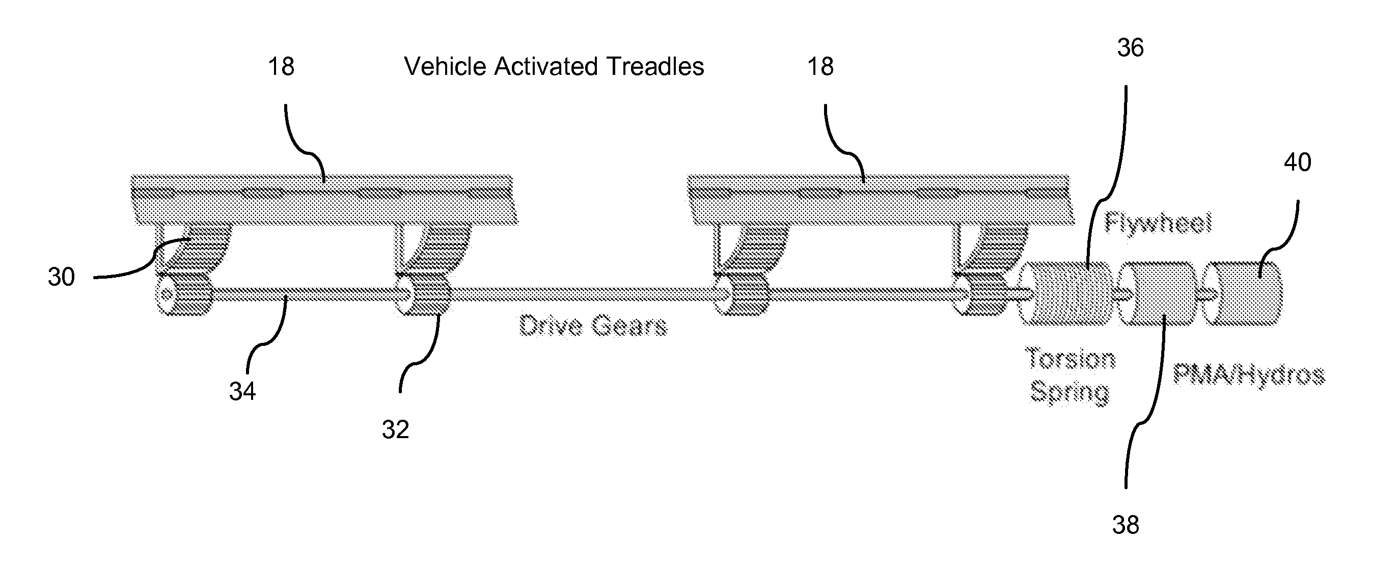
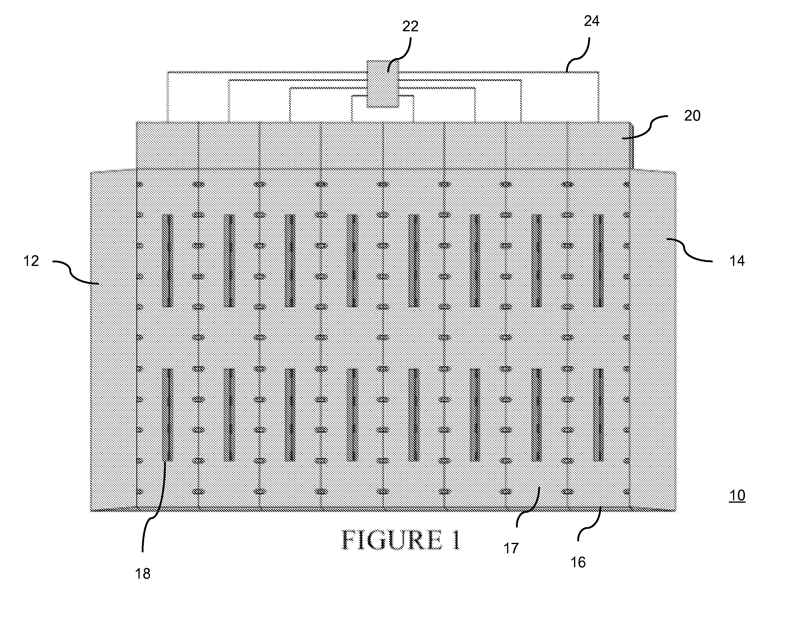
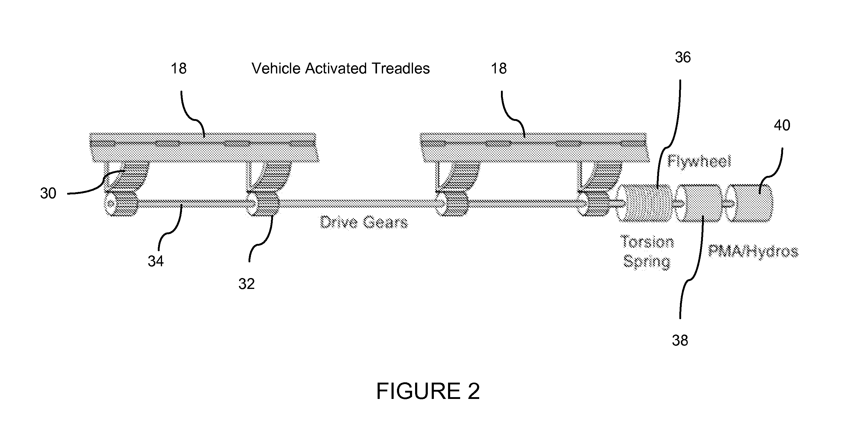
[0018]Referring now to the drawings, FIGS. 1-3 illustrate an exemplary vehicle energy harvester 10.

[0019]The exemplary embodiments can make productive use of the energy that is normally wasted (in the form of heat) in reducing the speed of motor vehicles on exit ramps, toll plazas etc., etc. The vehicle energy harvester 10 can absorb mechanical energy from passing (or breaking) vehicles and convert the mechanical energy to electrical energy using, for example, shaft driven generators. Other means for converting the me...


PUM


Abstract

A low-profile, surface mount vehicle energy harvester including a low-profile, surface mount subunit having an upper surface forming a roadway surface; a vehicle activated treadle on the subunit, the vehicle activated treadle moveable between a first position in which an upper surface of the treadle is at an angle with respect to the upper surface of the roadway surface and a second position in which the upper surface of the treadle is flush with the upper surface of the roadway surface; a generator that generates power in response to movement of the vehicle activated treadle; and an entry ramp at a first end of the harvester roadway surface; and an exit ramp at a second end of the harvester roadway surface.

Description

CROSS-REFERENCE TO RELATED APPLICATIONS[0001]The present invention claims the benefit of U.S. Provisional Patent Application No. 61 / 147,747, filed Jan. 27, 2009, and entitled “TRANSIENT ABSORBER FOR POWER GENERATION SYSTEM”, U.S. Provisional Patent Application No. 61 / 147,748, filed Jan. 27, 2009, and entitled “WEATHER RESPONSIVE TREADLE LOCKING MEANS FOR POWER GENERATION SYSTEM”, U.S. Provisional Patent Application No. 61 / 147,749, filed Jan. 27, 2009, and entitled “LOW PROFILE, SURFACE-MOUNTED POWER GENERATION SYSTEM”, U.S. Provisional Patent Application No. 61 / 147,750, filed Jan. 27, 2009, and entitled “VEHICLE SPEED DETECTION MEANS FOR POWER GENERATION SYSTEM”, U.S. Provisional Patent Application No. 61 / 147,752, filed Jan. 27, 2009, and entitled “RECIPROCAL SPRING ARRANGEMENT FOR POWER GENERATION SYSTEM”, and U.S. Provisional Patent Application No. 61 / 147,754, filed Jan. 27, 2009, and entitled “LOSSLESS SHORT-DURATION ELECTRICAL STORAGE MEANS FOR POWER GENERATION SYSTEM”, the enti...

Claims


Application Information

Patent Timeline
Patent Type & Authority Applications(United States)
IPC IPC(8): H02K7/18
CPCF03G7/08H02K7/025H02K7/07H02K7/116H02K7/1853
Inventor KENNEDY, EUGENE J.
Owner SOLARWINDOW TECH
Learn More