Distributed power system using direct current power sources

a technology of direct current and power supply, applied in the direction of emergency power supply arrangements, transportation and packaging, sustainable buildings, etc., can solve the problems of large conduction loss, inability to operate at best achievable efficiency, and inability to optimize the power draw of each individual panel

Active Publication Date: 2011-04-14
SOLAREDGE TECH LTD
View PDF99 Cites 220 Cited by
  • Summary
  • Abstract
  • Description
  • Claims
  • Application Information

AI Technical Summary

Benefits of technology

[0014]According to embodiments of the present invention there is provided a distributed power system including multiple (DC) batteries each DC battery with positive and negative poles. Multiple power converters are coupled respectively to the DC batteries. Each power converter includes a first terminal, a second terminal, a third terminal and a fourth terminal. The first terminal is adapted for coupling to the positive pole. The second terminal is adapted for coupling to the negative pole. The power converter includes: (i) a control loop adapted for setting the voltage between or current through the first and second terminals, and (ii) a power conversion portion adapted to selectively either: convert power from said first and second terminals to said third and fourth terminals to discharge the battery connected thereto, or to convert power from the third and fourth terminals to the first and second terminals to charge the battery connected thereto. Each of the power converters is adapted for serial connection to at least one other power converter by connecting respectively the third and fourth terminals, thereby forming a serial string. A power controller is adapted for coupling to the serial string. The power controller includes a control part adapted to maintain current through or voltage across the serial string at a predetermined value. The control part may maintain voltage across the serial string at a predetermined value or the control part may maintain current through the serial string at a predetermined value. The power controller may include a bi-directional DC/AC inverter or bi-directional DC/DC converter. The power converters may function as a current source, voltage regulator or trickle charge source. The distributed power system may further include multiple photovoltaic panels; multiple DC-DC converters. Each of the DC-to-DC converters may include input terminals coupled to a respective DC photovoltaic panels and output terminals coupled in series to the other DC-to-DC converters, thereby forming a second serial string. A control loop sets the voltage and/or current at the input terminals of the DC-to-DC converter according to predetermined criteria. A power conversion portion converts the power received at the input terminals to an output power at the output terminals. The serial string and the second serial string are connectible in parallel to form parallel-connected strings. A power controller may be adapted for coupling in parallel to the parallel-connected strings, the power controller including a contro

Problems solved by technology

Conversely, a serial connection may fail to provide the required current, so that several strings of serial connections may need to be connected in parallel to provide the required current.
For example, various inconsistencies in manufacturing may cause two identical sources to provide different output characteristics.
The problem facing the solar array designer is to produce a standard AC current at 120V or 220V root-mean-square (RMS) from a combination of the low voltages of the solar panels.
The delivery of high power from a low voltage requires very high currents, which cause large conduction losses on the order of the second power of the current (I2).
While this configuration is advantageous in terms of cost and architecture simplicity, several drawbacks have been identified in the literature for such architecture.
One recognized drawback is inefficiencie

Method used


Image

  • Distributed power system using direct current power sources
  • Distributed power system using direct current power sources
  • Distributed power system using direct current power sources

Examples


Embodiment Construction

[0027]Reference will now be made in detail to embodiments of the present invention, examples of which are illustrated in the accompanying drawings, wherein like reference numerals refer to the like elements throughout. The embodiments are described below to explain the present invention by referring to the figures.

[0028]Before explaining embodiments of the invention in detail, it is to be understood that the invention is not limited in its application to the details of design and the arrangement of the components set forth in the following description or illustrated in the drawings. The invention is capable of other embodiments or of being practiced or carried out in various ways. Also, it is to be understood that the phraseology and terminology employed herein is for the purpose of description and should not be regarded as limiting.

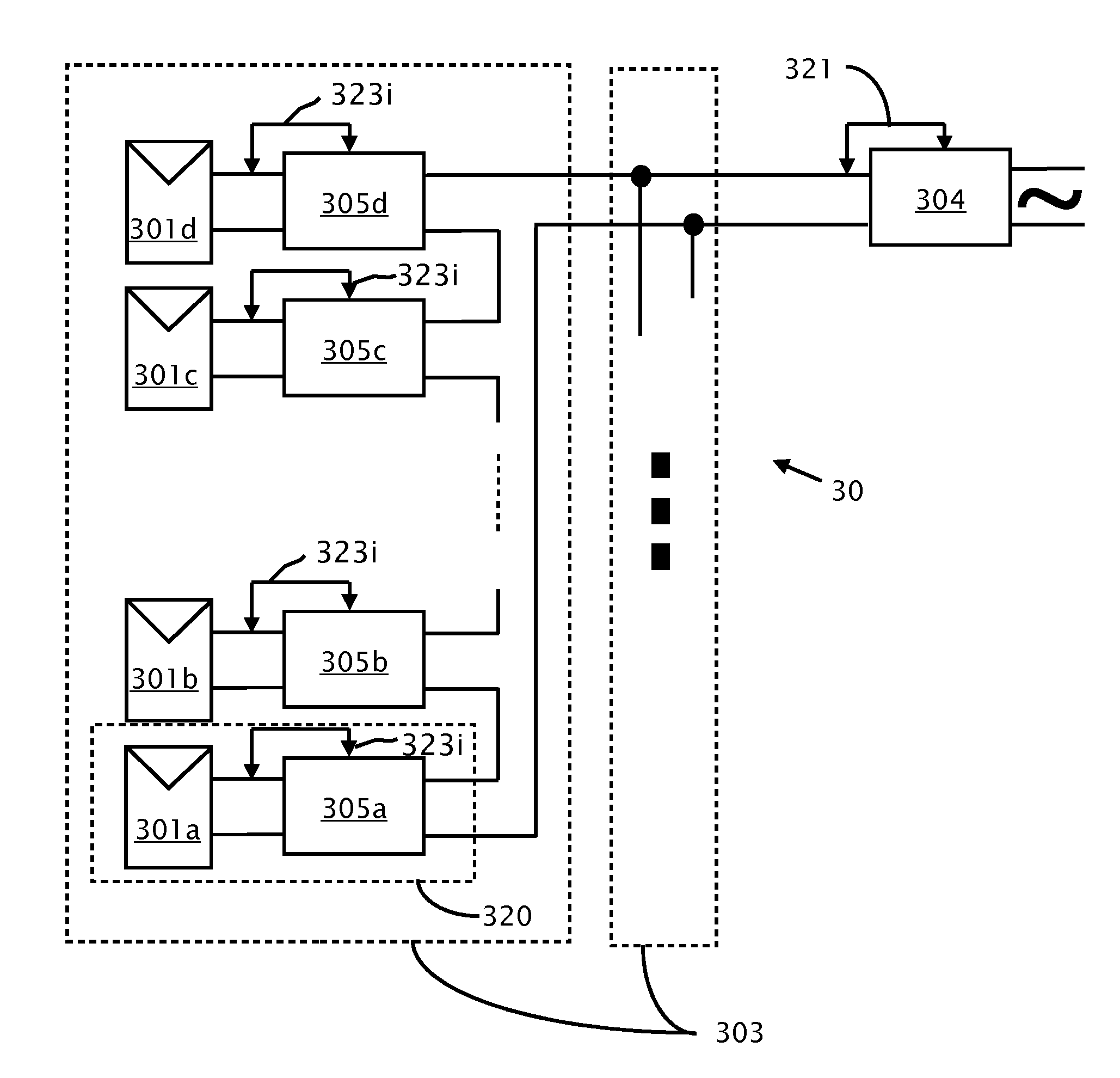
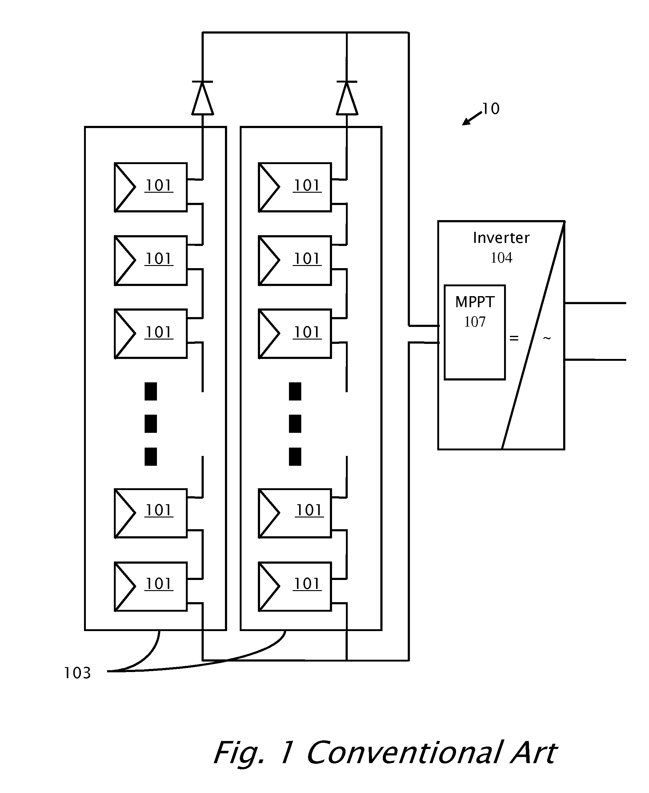
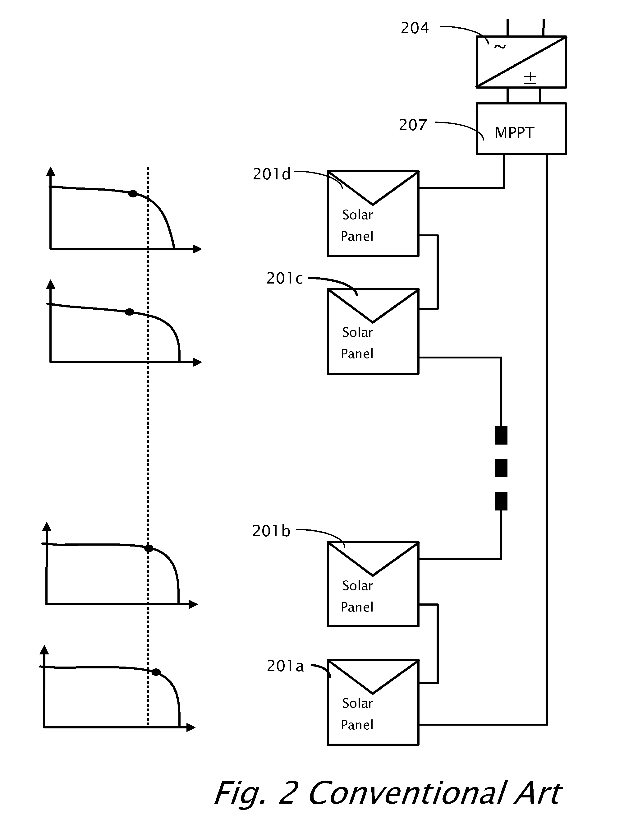
[0029]The topology provided by the subject invention solves many of the problems associated with, and has many advantages over, the conventional art top...


PUM


Abstract

A distributed power system including multiple (DC) batteries each DC battery with positive and negative poles. Multiple power converters are coupled respectively to the DC batteries. Each power converter includes a first terminal, a second terminal, a third terminal and a fourth terminal. The first terminal is adapted for coupling to the positive pole. The second terminal is adapted for coupling to the negative pole. The power converter includes: (i) a control loop adapted for setting the voltage between or current through the first and second terminals, and (ii) a power conversion portion adapted to selectively either: convert power from said first and second terminals to said third and fourth terminals to discharge the battery connected thereto, or to convert power from the third and fourth terminals to the first and second terminals to charge the battery connected thereto. Each of the power converters is adapted for serial connection to at least one other power converter by connecting respectively the third and fourth terminals, thereby forming a serial string. A power controller is adapted for coupling to the serial string. The power controller includes a control part adapted to maintain current through or voltage across the serial string at a predetermined value.

Description

CROSS REFERENCE TO RELATED APPLICATIONS[0001]The present application is a continuation-in-part application of U.S. patent application Ser. No. 11 / 950,271 filed Dec. 4, 2007 by the same inventors. The present application has the benefit of U.S. 61 / 254,681 filed on Oct. 24, 2009 by the same inventors the disclosure of which is included herein.BACKGROUND[0002]1. Technical Field[0003]The field of the invention relates generally to power production from distributed DC power sources, and more particularly to management of distributed DC power sources in series installations.[0004]2. Description of Related Art[0005]The recent increased interest in renewable energy has led to increased research in systems for distributed generation of energy, such as photovoltaic cells (PV), fuel cells, batteries (e.g., for hybrid cars), etc. Various topologies have been proposed for connecting these power sources to the load, taking into consideration various parameters, such as voltage / current requirement...

Claims


Application Information

Patent Timeline
IPC IPC(8): H02J1/00
CPCH02J1/102H02J3/383H02J7/35H02J7/0052Y02E10/566H02J1/00Y02E10/563H02J2300/24H02J3/381Y02B10/10Y02E10/56H02J2300/26H02J3/46H02J7/00H02J9/00
Inventor ADEST, MEIRHANDELSMAN, LIORGALIN, YOAVFISHELOV, AMIRSELLA, GUYBINDER, YARON
Owner SOLAREDGE TECH LTD
Why Eureka
Try Eureka