Oil tube with integrated heat shield

a heat shield and oil tube technology, applied in the direction of machines/engines, liquid fuel engines, manufacturing tools, etc., can solve the problems of space and weight requirements of conventional insulation systems for oil lines in mtf, and achieve the effect of reducing the number of parts

Active Publication Date: 2011-04-14
PRATT & WHITNEY CANADA CORP
View PDF28 Cites 74 Cited by
  • Summary
  • Abstract
  • Description
  • Claims
  • Application Information

AI Technical Summary

Benefits of technology

[0005]According to another aspect, provided is a gas turbine engine having an oil tube for delivering oil through a high temperature zone of the engine to an engine component, the oil tube comprising: a tubular body extending in a substantial length of the oil tube and axially between opposed end portions, each of the end portions ...

Problems solved by technology

The airfoils are exposed to the hot gas flow in the ITD and therefore an insulation system is demanded for the conduit because the hot temperature may cause lubricant degradat...

Method used


Image

  • Oil tube with integrated heat shield
  • Oil tube with integrated heat shield
  • Oil tube with integrated heat shield

Examples


Embodiment Construction

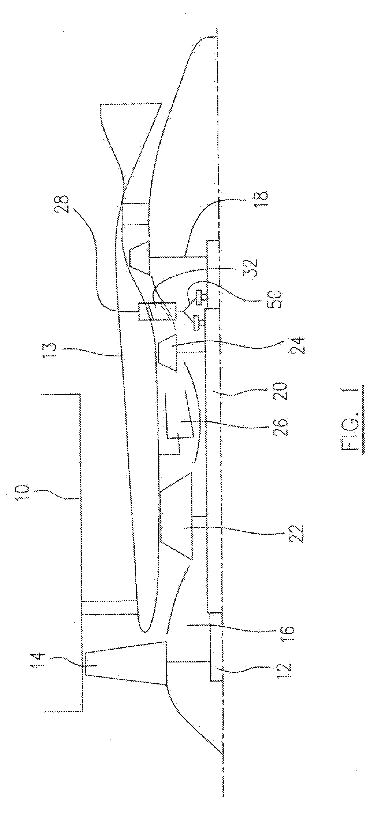
[0019]Referring to FIG. 1, a bypass gas turbine engine includes a fan case 10, a core casing 13, a low pressure spool assembly which includes a fan assembly 14, a low pressure compressor assembly 16 and a low pressure turbine assembly 18 connected by a shaft 12 and a high pressure spool assembly which includes a high pressure compressor assembly 22 and a high pressure turbine assembly 24 connected by a turbine shaft 20. The core casing 13 surrounds the low and high pressure spool assemblies to define a main fluid path therethrough. In the main fluid path there is provided a combustor 26 which generates combustion gases to power the high pressure turbine assembly 24 and the low pressure turbine assembly 18. A mid turbine frame (MTF) 28 includes an inter-turbine duct (ITD) 32 disposed between the high pressure turbine assembly 24 and the low pressure turbine assembly 18 and supports a bearing housing 50 for accommodating bearings around the respective shafts 20 and 12.

[0020]Referring ...


PUM

PropertyMeasurementUnit
Temperatureaaaaaaaaaa
Lengthaaaaaaaaaa
Shapeaaaaaaaaaa

Abstract

A gas turbine engine has an oil tube for delivering oil through a high temperature zone of the engine to an engine component for cooling and lubrication. An insulation tube surrounds the oil tube and extends in a substantial length of the oil tube. The opposed ends of the insulation tube are integrally and sealingly connected to respective end portions of the oil tube to form a dead air annulus between the oil tube and the insulation tube.

Description

TECHNICAL FIELD[0001]The invention relates generally to gas turbine engines and, more particularly, to a gas turbine engine having a heat insulation system for an oil tube.BACKGROUND OF THE ART[0002]A mid turbine frame (MTF), sometimes referred to as an inter turbine frame, is located generally between turbine stages of a gas turbine engine to support one or more bearings and to transfer bearing loads through to the outer engine case, and also to form an inter-turbine duct (ITD) for directing a hot gas flow to the downstream rotor. It is conventional to have a conduit carrying a lubricant fluid to pass through one of the radial hollow airfoils disposed in the ITD. The airfoils are exposed to the hot gas flow in the ITD and therefore an insulation system is demanded for the conduit because the hot temperature may cause lubricant degradation or even lubricant ignition if lubricant leakage occurs. Conventional insulation systems for oil lines in MTF has relatively complicated structure...

Claims


Application Information

Patent Timeline
IPC IPC(8): F01D5/08B23P15/26
CPCF01M11/02Y10T29/49393F16L59/143F01D9/065
Inventor DUROCHER, ERICWATSON, JOHN
Owner PRATT & WHITNEY CANADA CORP
Why Eureka
Try Eureka