[0018]
Lumbar arthrodesis is often utilized to treat a variety of degenerative spinal conditions. Posterior approaches have traditionally been used, with varying degrees of success. Posterior approaches can be associated with significant morbidity however. Prolonged
muscle dissection and retraction can result in
paraspinal muscle atrophy and
fibrosis, which may result in prolonged pain and disability. As a result, an anterior or
lateral approach, disectomy and interbody fusion has been advocated by many as an alternative to posterior arthrodesis. Generally, a more complete disectomy can be performed, which may provide a better surface area for fusion, as well as a larger cross-sectional area in which to sustain load and
resist subsidence. Anterior
lumbar arthrodesis may result in improved expansion of the
disc space and increased local disc angle, which may improve spinal sagittal balance more effectively than posterior
lumbar arthrodesis.
[0019]Oftentimes however, anterior or lateral interbody fusion requires supplemental
instrumentation to increase stability. In the case of the
lateral approach to lumber fusion, a lateral lumber plate can be used at the time of interbody fusion, but because only the lateral aspect of the anterior
lumbar bodies are being fixated on one side, transitional forces may be turned into shear or rotation, and may be biomechanically suboptimal. For the same reason, unilaterally placed
pedicle screw rod fixation in the
lateral position suffers from the same constraints. Many surgeons feel that
facet screws, or midline interspinous process fixation, is required to maximize stability and minimize the risk of construct failure. Currently the only way to achieve that goal is to place the patient in the
prone position, and perform a second operation. This adds significant overall time to the
surgery, and also requires one or more new incisions in the back to place the
instrumentation, with its associated
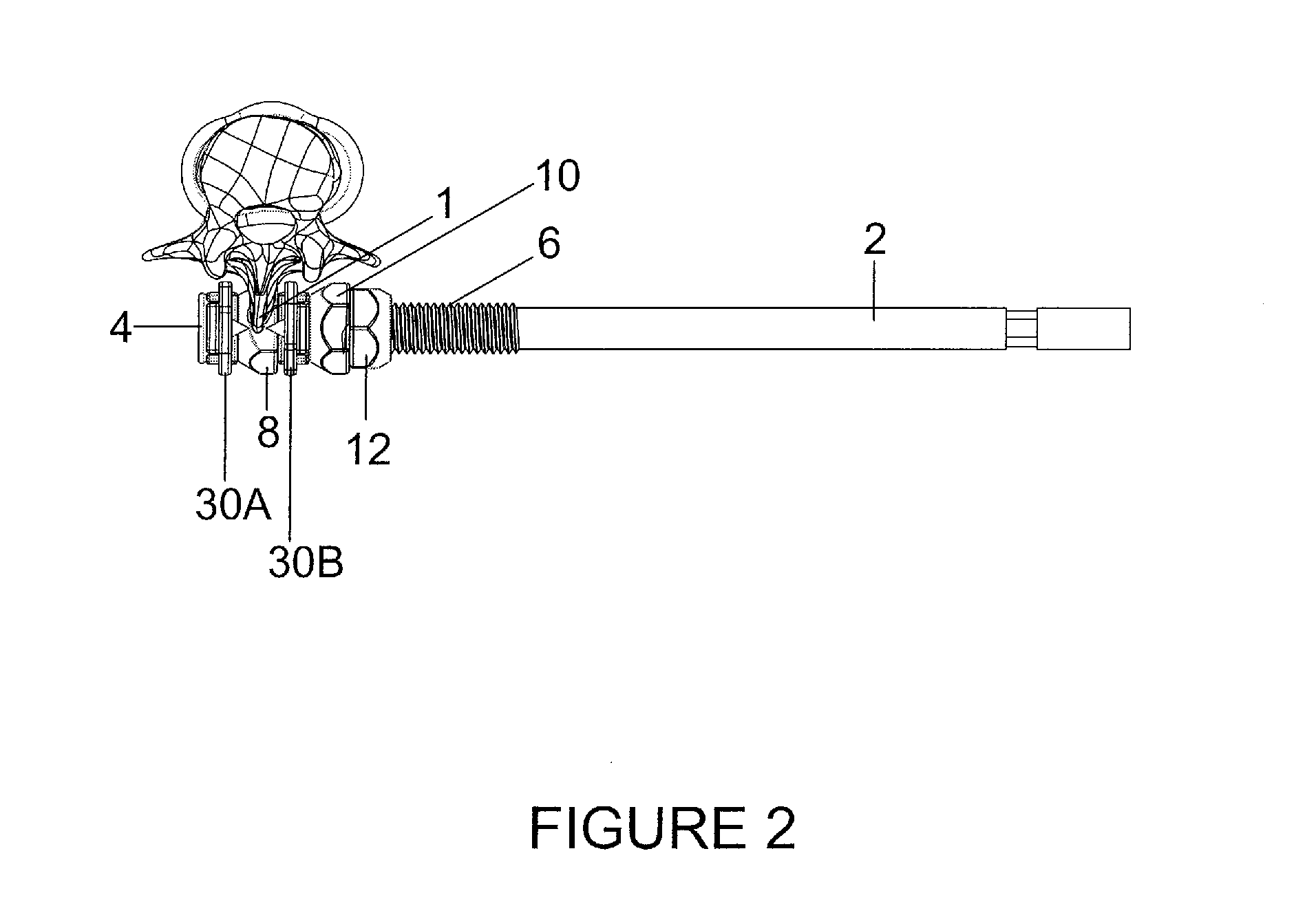
increased risk and morbidity. Ideally, if a method could be devised where midline
posterior fixation can be obtained while the patient is already in the
lateral position, then one could reduce the patient's
operative time, risk and mobility, while at the same time increasing overall construct stability. A laterally placed minimally invasive intraspinous fixation device would ideally address that situation. Such an intraspinous device could be placed without any additional incisions and without the time necessary to place the patient in the
prone position for a second operation. Moreover, because no posterior incision is required, there is a complete preservation of the posterior
tension band, including the paraspinal muscles and the supraspinous
ligament. Prior to this invention no such device exists in the field.
[0021]It is a further objective of the instant invention to provide a
spinous process plate that can be positioned and installed without the removal of the supraspinous
ligament, and the paraspinal muscles.
[0022]It is yet another objective of the instant invention to provide a spinous fixation device that will reduce the risk of morbidity, reduce the patients'
operative time, and decrease the amount of time required for recuperation.

