Surface treating appliance

a surface treatment and appliance technology, applied in the direction of suction cleaners, motor fan assembly mounting, cleaning equipment, etc., can solve the problem of restricting the maneuverability of vacuum cleaners through narrow spaces, and achieve the effect of improving compromising the maneuverability of appliances

Active Publication Date: 2011-04-21
DYSON TECH LTD
View PDF95 Cites 31 Cited by
  • Summary
  • Abstract
  • Description
  • Claims
  • Application Information

AI Technical Summary

Benefits of technology

[0010]The location of the yoke between the rims of the wheels of a substantially spherical support assembly can improve the maneuverability of the appliance through narrow spaces, and can provide the appliance with a compact appearance. The provision of a pair of dome-shaped wheels instead of a barrel can enable structural features, fluid flow paths and electrical connectors of the appliance to pass between the wheels of the support assembly to components located within a volume at least partially delimited by the outer surfaces of the wheels without the

Problems solved by technology

The provision of both ducting and a yoke extending around the periphery of the rolling assembly can restri

Method used


Image

  • Surface treating appliance
  • Surface treating appliance
  • Surface treating appliance

Examples


Embodiment Construction

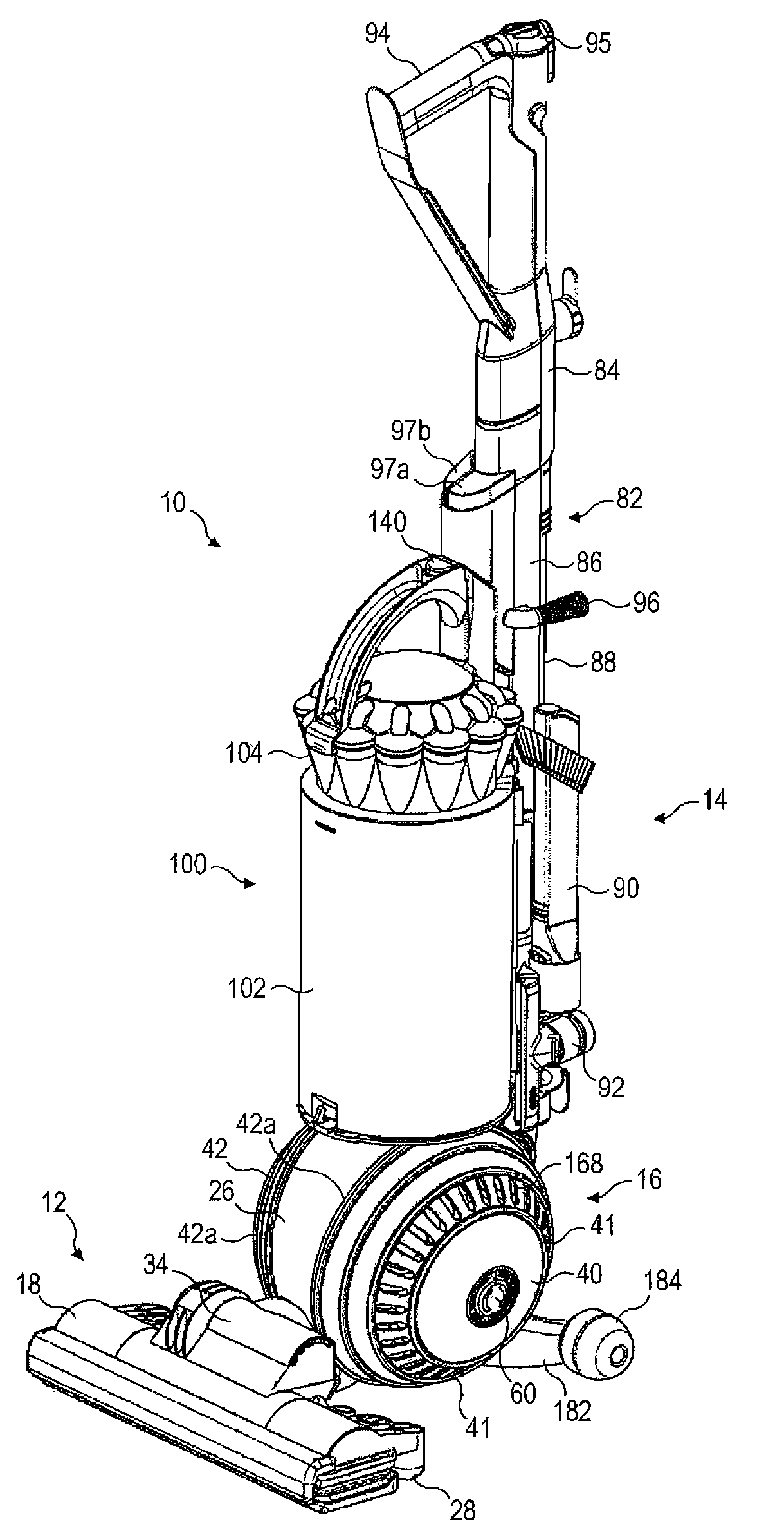
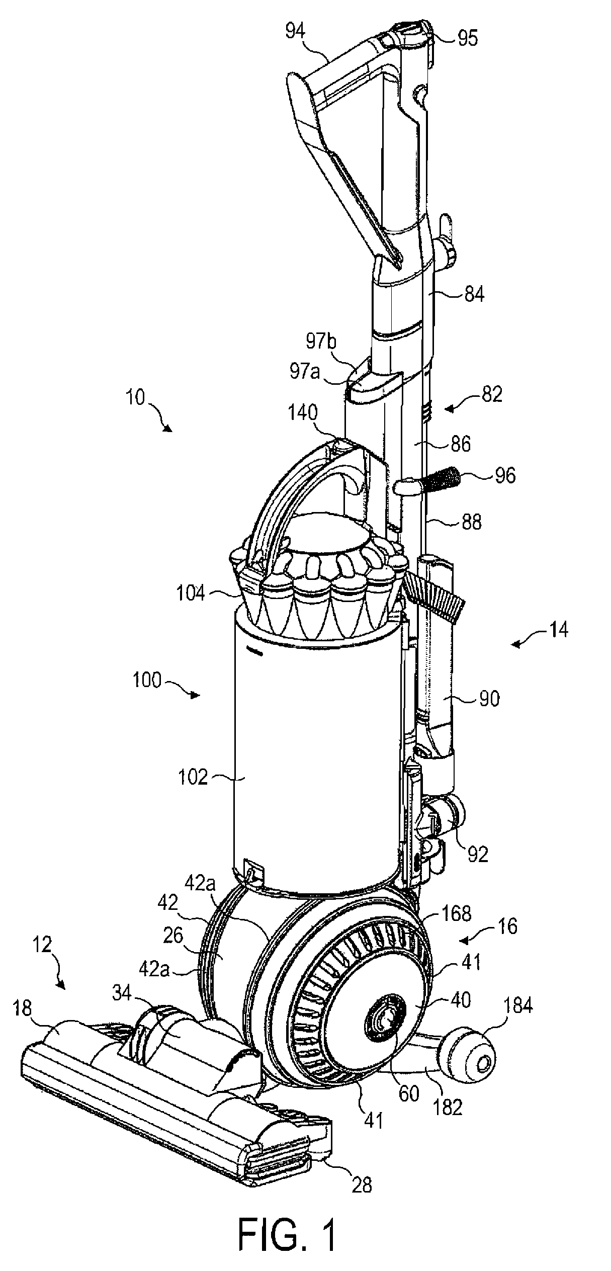
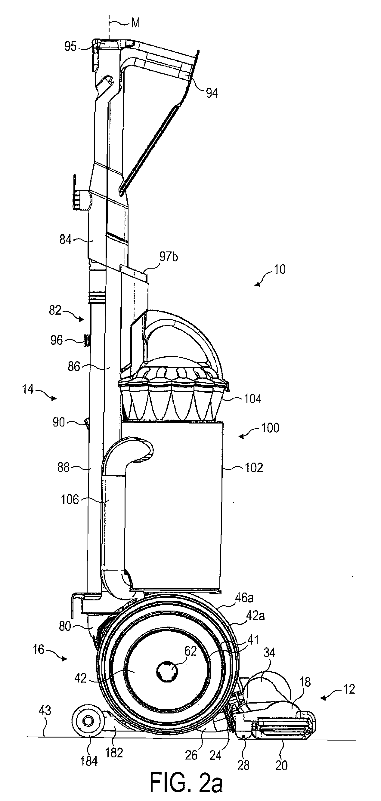
[0040]FIGS. 1 to 4 illustrate an upright surface treating appliance, which is in the form of an upright vacuum cleaner. The vacuum cleaner 10 comprises a cleaner head 12, a main body 14 and a support assembly 16. In the FIGS. 1, 2a, 3 and 4, the main body 14 of the vacuum cleaner 10 is in an upright position relative to the cleaner head 12, whereas in FIG. 2b the main body 14 is in a fully reclined position relative to the cleaner head 12.

[0041]The cleaner head 12 comprises a housing 18 and a lower plate, or sole plate 20, connected to the housing 18. The sole plate 20 comprises a suction opening 22 through which a dirt-bearing air flow enters the cleaner head 12. The sole plate 20 has a bottom surface which, in use, faces a floor surface to be cleaned, and which comprises working edges for engaging fibers of a carpeted floor surface. The housing 18 defines a suction passage extending from the suction opening 22 to a fluid outlet 24 located at the rear of the housing 18. The fluid o...


PUM


Abstract

An upright surface treating appliance includes a main body having a user operable handle, and a support assembly for allowing the appliance to be rolled along a surface using the handle. The support assembly includes a yoke pivotably connected to the main body, and a pair of domed-shaped wheels rotatably connected to the yoke. A surface treating head is connected to the yoke. The yoke is shaped so that a section of the yoke is located between the rims of the wheels. To afford a compact appearance to the appliance, the outer surfaces of the wheels and the section of the yoke together at least partially delimit a substantially spherical volume.

Description

REFERENCE TO RELATED APPLICATIONS[0001]This application claims the priority of United Kingdom Application No. 0918035.7, filed Oct. 15, 2009, the entire contents of which are incorporated herein by reference.FIELD OF THE INVENTION[0002]The present invention relates to a surface treating appliance, and in its preferred embodiment relates to an upright vacuum cleaning appliance.BACKGROUND OF THE INVENTION[0003]Surface treating appliances such as vacuum cleaners are well known. The majority of vacuum cleaners are either of the “upright” type or of the “cylinder” type (also referred to canister or barrel machines in some countries). An upright vacuum cleaner typically comprises a main body containing dirt and dust separating apparatus, a pair of wheels mounted on the main body for maneuvering the vacuum cleaner over a floor surface to be cleaned, and a cleaner head mounted on the main body. The cleaner head has a downwardly directed suction opening which faces the floor surface. The vac...

Claims


Application Information

Patent Timeline
IPC IPC(8): A47L9/00
CPCA47L5/32A47L9/22A47L9/009A47L9/0054A47L5/28
Inventor DYSON, JAMESGAMMACK, PETER DAVIDCOURTNEY, STEPHEN BENJAMINNEWTON, DAVID CHRISTOPHER JAMESCZERPAK, SAMUEL JAMESJOYNT, MICHAEL SEAN
Owner DYSON TECH LTD
Why Eureka
Try Eureka