Air conditioning apparatus

a technology of air conditioning apparatus and refrigerant concentration, which is applied in the direction of lighting and heating apparatus, refrigerating machines, compression machines with reversible cycles, etc., can solve the problems of refrigerant concentration in the space exceeding and the above-described allowable concentration may still be exceeded

Active Publication Date: 2011-04-21
MITSUBISHI ELECTRIC CORP
View PDF9 Cites 46 Cited by
  • Summary
  • Abstract
  • Description
  • Claims
  • Application Information

AI Technical Summary

Benefits of technology

[0011]In the present invention, at least one of the water and the antifreeze solution circulates in at least one of the plurality of user-side refrigerant circuits. Therefore, the refrigerant whose allowable concentration is kept under control is prevented from leaking into a space where people exist by circulating at least one of the water and the antifreeze solution in the user-side refrigerant circuit installed in, for example, the space where people exist (living spaces, or spaces where people come and go, etc.). With the configuration of this refrigerant circuit, the plurality of indoor units are capable of performing a cooling and heating simultaneous operation.

Problems solved by technology

Therefore, there is a problem that when the refrigerant leaks into the space such as the room, the refrigerant concentration in the space may exceed the above-described allowable concentration.
However, there still remains a problem that when the refrigerant leaks in the space such as the room, the refrigerant concentration in the space may still exceed the above-described allowable concentrations.

Method used


Image

  • Air conditioning apparatus
  • Air conditioning apparatus
  • Air conditioning apparatus

Examples


embodiment 1

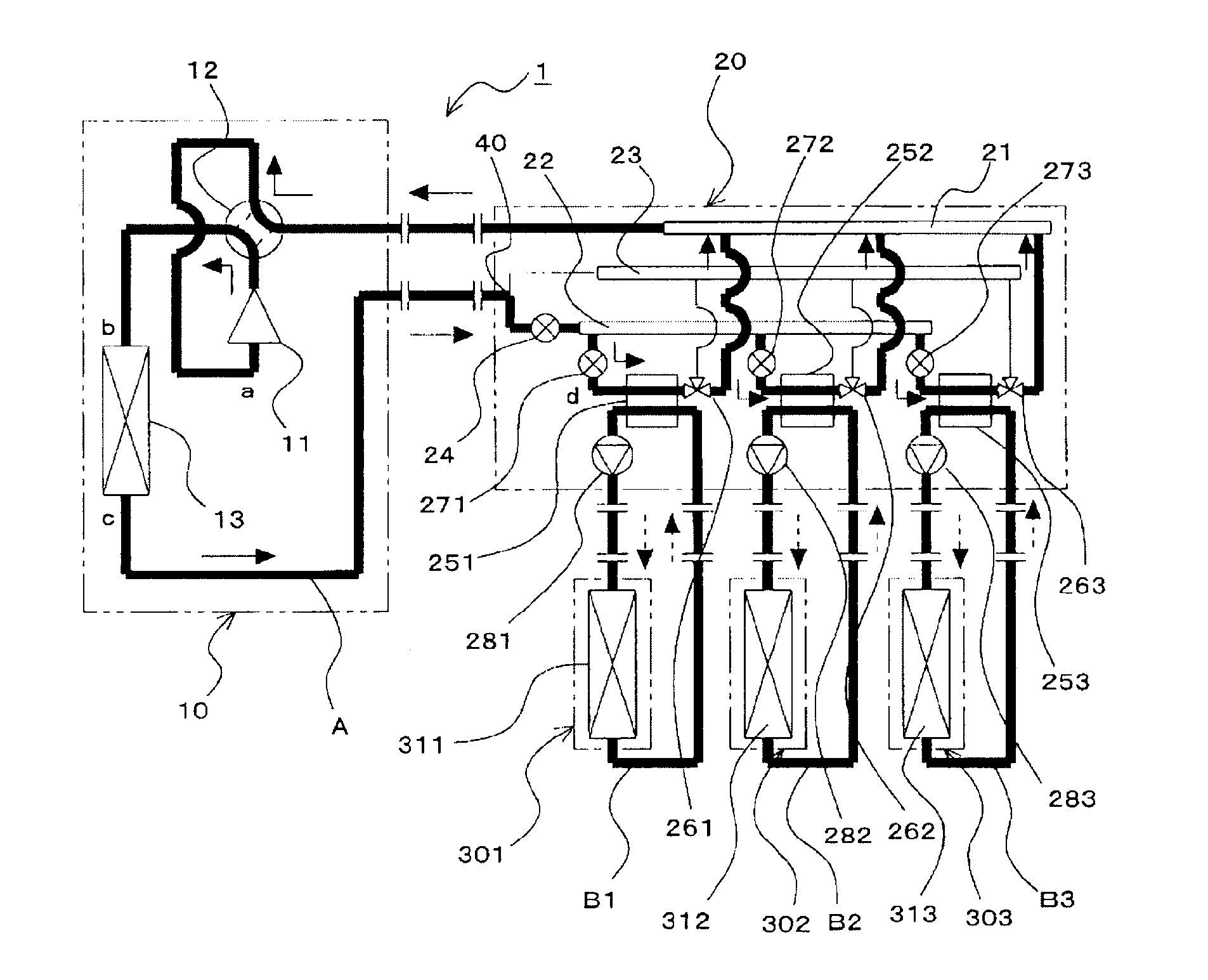
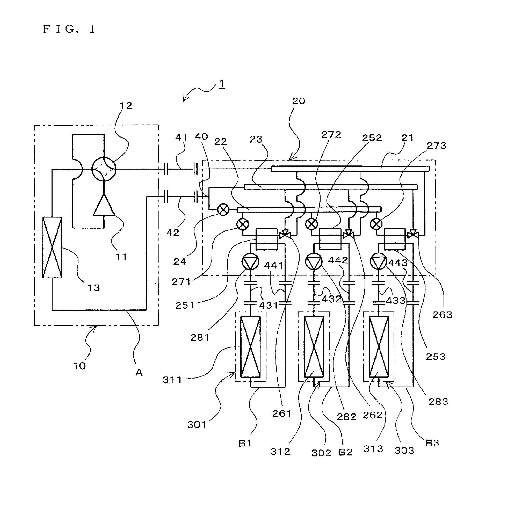
[0051]FIG. 1 is a refrigerant circuit diagram of an air conditioning apparatus according to Embodiment 1 in the present invention.

[0052]An air conditioning apparatus 1 includes a heat source-side refrigerant circuit A having an outdoor heat exchanger 13 configured to perform a heat exchange with outdoor air, and user-side refrigerant circuits Bn having indoor heat exchangers 31n (hereinafter, n represents 1 and larger natural numbers, and represents the number of units of the indoor heat exchangers) configured to perform the heat exchange with indoor air. A heat source-side refrigerant circulating in the heat source-side refrigerant circuit A and the user-side refrigerant circulating in the user-side refrigerant circuits Bn perform the heat exchange each other in intermediate heat exchangers 25n. Then, respective components in the heat source-side refrigerant circuit A and the user-side refrigerant circuits Bn are provided in an outdoor unit 10, a relay unit 20, and indoor units 30n...

embodiment 2

[0118]FIG. 10 is a refrigerant circuit diagram of the air conditioning apparatus according to Embodiment 2 in the present invention. The air conditioning apparatus 1 includes a refrigerant flow channel switching unit 50, a gas-liquid separating device 61, bypass piping 62, and a third refrigerant flow rate control device 63 in the refrigerant circuit in the air conditioning apparatus in Embodiment 1. A refrigerant which dissipates heat while condensing is used in the heat source-side refrigerant circuit A in the air conditioning apparatus 1. Here, the refrigerant flow channel switching unit 50 corresponds to the third refrigerant flow channel switching device in the present invention.

[0119]In Embodiment 2, items which are not specifically noted are the same as those in Embodiment 1, and the same functions and configurations will be described using the same reference numerals.

[0120]The refrigerant flow channel switching unit 50 is provided in the outdoor unit 10, and includes a first...

embodiment 3

[0171]Although the flow rate of the water flowing in the user-side refrigerant circuits B1-B3 is not controlled in Embodiment 1 and Embodiment 2, the user-side refrigerant circuits B1-B3 may be configured to control the flow rate of the water flowing in the user-side refrigerant circuits B1-B3.

[0172]FIG. 19 is a refrigerant circuit diagram of the air conditioning apparatus according to Embodiment 3 in the present invention. The air conditioning apparatus 1 is provided with first temperature sensors 641-643, the second temperature sensors 651-653, and inverters 661-663 in the user-side refrigerant circuit in the air conditioning apparatus 1 shown in Embodiment 1. Here, the inverters 661-663 correspond to the fourth refrigerant flow rate control device in the present invention.

[0173]The first temperature sensors 641-643 are provided in the inlet-side piping (relay unit side) of the indoor heat exchangers 311-313 respectively for detecting the temperature of the water flowing into the ...


PUM


Abstract

A heat source-side refrigerant circuit A including a compressor 11, an outdoor heat exchanger 13, a first refrigerant branch portion 21 connected to the compressor 11, a second refrigerant branch portion 22 and a third refrigerant branch portion 23 connected to the outdoor heat exchanger 13, a first refrigerant flow rate control device 24 provided between branch piping 40 and the second refrigerant branch portion 22, intermediate heat exchangers 25n connected at one side thereof to the first refrigerant branch portion 21 and the third refrigerant branch portion 23 via three-way valves 26n and connected at the other side thereof to the second refrigerant branch portion 22, and second refrigerant flow rate control devices 27n provided between the respective intermediate heat exchangers 25n and the second refrigerant branch portion 22, and user-side refrigerant circuits Bn having indoor heat exchangers 31n connected respectively to the intermediate heat exchangers 25n are provided, and at least one of water and an antifreeze solution circulates in the user-side refrigerant circuits Bn.

Description

TECHNICAL FIELD[0001]The present invention relates to an air conditioning apparatus, and more specifically, to a multi-chamber type air conditioning apparatus having a plurality of indoor units and being capable of performing a cooling-heating simultaneous operation.BACKGROUND ART[0002]As a multi-chamber type air conditioning apparatus in the related art having a plurality of indoor units and being capable of performing a cooling-heating simultaneous operation, for example, a configuration such as “Reference numeral (1) designates a compressor, (2) designates a four-way valve configured to switch the direction of flow of a refrigerant in a heat source unit, (3) designates a heat source unit-side heat exchanger, and (4) designates an accumulator being connected to the apparatuses (1) to (3), whereby a heat source unit (A) is configured. Reference numeral (5) designates three indoor-side heat exchangers, (6) designates first connecting piping that connects the four-way valve (2) of th...

Claims


Application Information

Patent Timeline
Patent Type & Authority Applications(United States)
IPC IPC(8): F25B27/00F25B13/00F25B43/00
CPCF25B13/00F25B25/005F25B2313/02741F25B2313/0231F25B2313/0272F25B2313/006
Inventor WAKAMOTO, SHINICHIYAMASHITA, KOJIOKAZAKI, TAKASHITANAKA, NAOKIHOKAZONO, KEISUKEMORIMOTO, HIROYUKIMOTOMURA, YUJIHATOMURA, TAKESHIKASAI, TOMOHIKOTAKENAKA, NAOFUMISHIMAZU, YUSUKE
Owner MITSUBISHI ELECTRIC CORP
Why Eureka
Try Eureka