Load measuring sensor for rod-shaped body and load measuring system

Inactive Publication Date: 2011-04-21
HITACHI CABLE
View PDF9 Cites 26 Cited by
  • Summary
  • Abstract
  • Description
  • Claims
  • Application Information

AI Technical Summary

Benefits of technology

[0041](1) It is excellent in workability for installation.
[0042](2) It is excellent in vibration, heat (or high-temperature) and humidity resistance.
[0043](3) It provides less limitation in securing a portion to which the sensor is attached.

Problems solved by technology

In the technique of the non-patent literature 1 in which the strain sensor, etc., is attached directly to the suspension, assembly of the strain sensor is complicated, position accuracy of the strain sensor is difficult to control, calibration after the assembly of the st

Method used


Image

  • Load measuring sensor for rod-shaped body and load measuring system
  • Load measuring sensor for rod-shaped body and load measuring system
  • Load measuring sensor for rod-shaped body and load measuring system

Examples


Embodiment Construction

[0061]A preferred embodiment of the invention will be described in detail below in conjunction with the appended drawings.

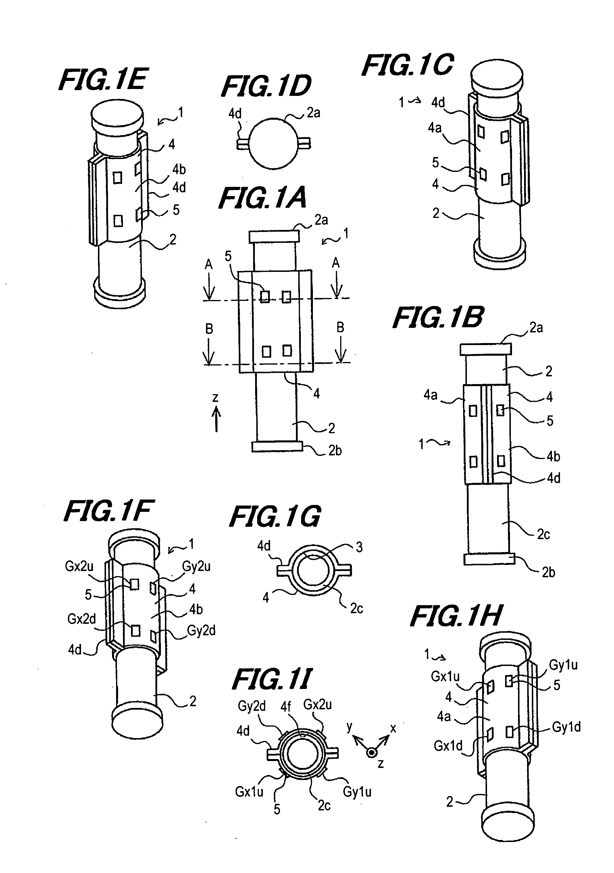
[0062]As shown in FIGS. 1A to 1I, a load measuring sensor 1 for rod-shaped body according to the invention is provided with a stress transfer member 4 having portions tightly fixed to at least two longitudinal positions of a rod-shaped body 2 which is deformable by a load (load transmitting portions 3) and a non-attached portion (a portion between two load transmitting portions 3), and plural strain gauges 5 attached to the stress transfer member 4 at plural circumferential positions of each of two longitudinal positions.

[0063]Rigidity (bending rigidity, tensile / compressive rigidity or torsional rigidity) of the stress transfer member 4 is preferably smaller than that of the rod-shaped body 2.

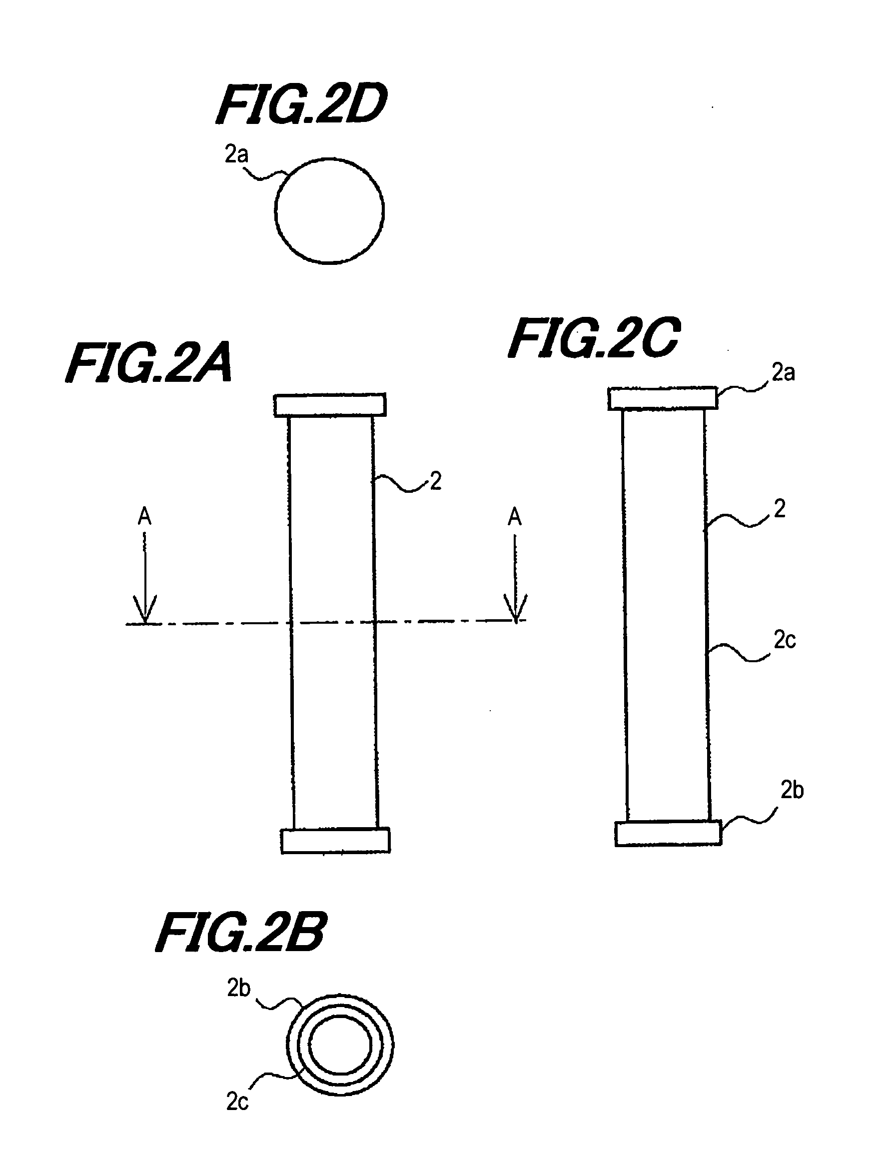
[0064]In the present embodiment, the rod-shaped body 2 is a cylinder or a cylindrical body having a circular cross-section as shown in FIGS. 2A to 2C, which is hereinafter r...


PUM


Abstract

A load measuring sensor for a rod-shaped body includes a stress transfer member including portions tightly fixed to the rod-shaped body at two longitudinal positions and a non-fixed portion not fixed to the rod-shaped body, the rod-shaped body being deformable by a load, and a plurality of strain gauges each attached to the stress transfer member at a plurality of circumferential positions of the stress transfer member and at least two longitudinal positions of the stress transfer member.

Description

[0001]The present application is based on Japanese Patent Application No. 2009-239425 filed on Oct. 16, 2009, the entire contents of which are incorporated herein by reference.BACKGROUND OF THE INVENTION[0002]1. Field of the Invention[0003]The invention relates to a load measuring sensor for a rod-shaped body being suitably applicable to a rod-shaped body, as well as a load measuring system.[0004]2. Description of the Related Art[0005]Recognizing a load from a road surface associated with movement is required to control movement of a vehicle. The load from the road surface is transmitted to a vehicle body via a tire, a hub and a suspension composing a shock absorber, etc. When the load is inputted to each member located on a load transmission path, stress or movement is generated in the member, and the member is deformed due to the stress. The deformation can be measured by a strain gauge or a displacement sensor, etc., and the movement can be measured by an acceleration sensor, etc...

Claims


Application Information

Patent Timeline
IPC IPC(8): G01L1/22
CPCG01L5/161G01L1/2218G01L5/1627
Inventor YAMAMOTO, SATOSHI
Owner HITACHI CABLE
Why Eureka
Try Eureka